Front Panel Operation
3-29
AC current measurements
The Model 2001 can make AC current measurements be-
tween 100pA and 2.1A. Assuming “bench reset” conditions
(see paragraph 3.12.1), the basic procedure is as follows:
1. Connect the test leads to the AMPS and INPUT LO ter-
minals of the Model 2001. Either the front or rear inputs
can be used; place the INPUTS button in the appropriate
position.
2. Select the ACI function.
3. Select a range consistent with the expected current. For
automatic range selection, press the AUTO key. The
AUTO annunciator denotes whether auto-ranging is en-
abled.
4. Connect the test leads to the source as shown in Figure
3-11.
CAUTION
Do not apply more than 2.1A, 250V to
the AMPS input, or the amps protection
fuse will blow.
5. Observe the display. If the “Overflow” message is
shown, select a higher range until a normal reading is
displayed. Always use the lowest possible range for the
best resolution.
6. Take a reading from the display.
AMPS fuse replacement
There are two protection fuses for the current ranges, one for
the front terminals, another for the rear. This procedure de-
scribes how to change an AMPS fuse.
WARNING
Make sure the instrument is disconnect-
ed from the power line and other equip-
ment before replacing an AMPS fuse.
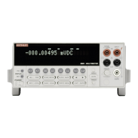
Figure 3-11
DC and AC current measurements
NEXT
DISPLAY
PREV
POWER
DCV ACV DCI ACI Ω2 Ω4
FREQ TEMP
REL TRIG STORE RECALL
INFO LOCAL CHAN SCAN CONFIG MENU EXIT ENTER
RANGE
AUTO
FILTER MATH
RANGE
2001 MULTIMETER
SENSE
Ω 4 WIRE
HI
INPUT
LO
INPUTS
CAL
500V
PEAK
F
R
FRONT/REAR
2A 250V
AMPS
350V
PEAK
1100V
PEAK
Model 2001
Caution : Maximum Input = 2.1A
Current
Source
+000.0050 µADC
Range: 200 µADC
1. Turn off the power and disconnect the power line and
test leads.
2. Perform one of the following steps:
A. For the front panel AMPS fuse, gently push in the
AMPS jack with your thumb and rotate the fuse car-
rier one-quarter turn counter-clockwise. Release
pressure on the jack and its internal spring will push
the jack out of the socket.
B. For the rear panel AMPS fuse, place the end of a
flat-blade screwdriver into the rear panel AMPS
holder. Push in gently and rotate the fuse carrier
one-quarter turn counter-clockwise. Release pres-
sure on the holder and its internal spring will push
the fuse carrier out of the holder.
3. Remove the fuse and replace it with the same type (2A,
250V, fast blow, 5
×
20mm). The Keithley part number
is FU-48.
CAUTION
Do not use a fuse with a higher current
rating than specified, or instrument
damage may occur. If the instrument re-
peatedly blows fuses, locate and correct
the cause of the trouble before replacing
the fuse. See the optional Model 2001
Repair Manual for troubleshooting in-
formation.
4. Install the new fuse by reversing the above procedure.

 Loading...