IEEE-488 Reference
4-11
Bit B1 in the Arm Event Register is unmasked when the cor-
responding bit (B1) in the Arm Event Enable Register is set
(1). When the unmasked bit of the Arm Event Register sets,
it is ANDed with the corresponding set bit in the Arm Event
Enable Register. The logic “1” output of the AND gate is ap-
plied to the input of the OR gate and thus, will set the Waiting
for Arm bit in the Operation Condition Register.
Bit B1 of the Arm Event Enable Register can be set or
cleared by using the following SCPI command:
:STATus:OPERation:ARM:ENABle <NRf>
The following SCPI query command can be used to read the
Arm Event Enable Register:
:STATus:OPERation:ARM:ENABle?
Reading this register using the above SCPI command will
not clear the register. The following list summarizes opera-
tions that will clear the Arm Event Enable Register:
1. Cycling power.
2. Sending the :STATus:OPERation:ARM:ENABle 0
command.
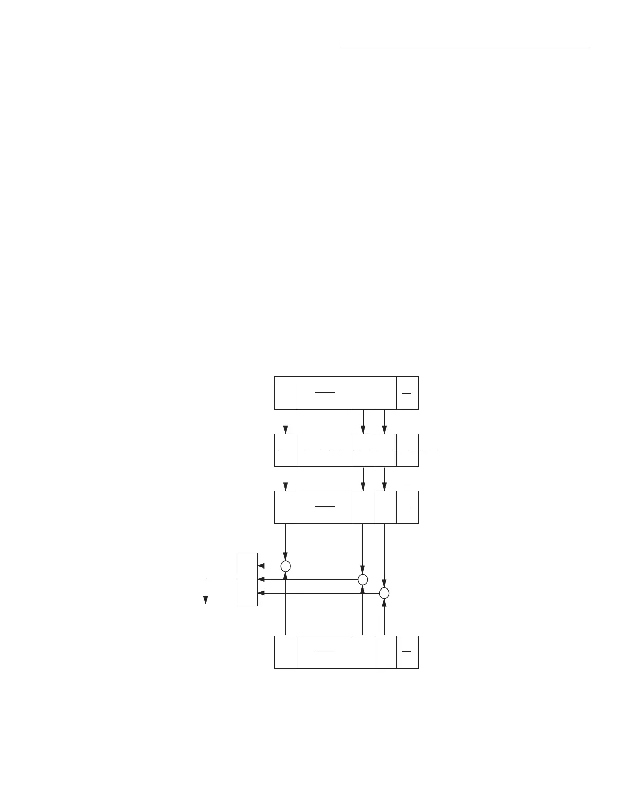
4.6.4 Sequence event status
The reporting of sequence events is controlled by a set of 16-
bit registers; the Sequence Condition Register, the Transition
Filter, the Sequence Event Register and the Sequence Event
Enable Register. Figure 4-9 shows how these registers are
structured.
Two bits of this register set are used by the Model 2001 to re-
port sequence events. Bit B1 (In arm layer 1) is set when in-
strument is in (or exited) the arm layer (arm layer 1) of
operation. Bit B2 (In arm layer 2) is set when the instrument
is in (or exited) the scan layer (arm layer 2). The operation
process over the bus is explained in paragraph 4.7.
The various registers used for sequence event status are de-
scribed as follows. Note that these registers are controlled by
the :STATus:OPERation:ARM:SEQuence commands of the
:STATus subsystem (see paragraph 4.21).
(B14 - B3)
(B15) (B2)
(B1) (B0)
OR
Sequence
Condition Register
Sequence Event
Enable Register
Lay1 = Layer 1 (Set bit indicates that 2001 is
in arm layer 1).
Lay2 = Layer 2 (Set bit indicates that 2001 is
in arm layer 2).
&
&
&
0
Lay2 Lay1
(B14 - B3)
(B15) (B2)
(B1) (B0)
0
Lay2 Lay1
(B14 - B3)
(B15) (B2)
(B1) (B0)
0
Always
Zero
Lay2 Lay1
PTR
NTR
Sequence
Transition Filter
Sequence Event
Register
(B14 - B3)
(B15) (B2) (B1) (B0)
Lay2 Lay1
To Sequence 1 Bit
(Seq 1) of Arm
Event Condition
Register (See
Figure 4-8).
= Logical AND
= Logical OR
= Positive Transition Register
= Negative Transition Register
&
OR
PTR
NTR
igure 4-9
Sequence event status

 Loading...


