IEEE-488 Reference
4-13
Reading this register using the above SCPI command will
not clear the register. The following list summarizes opera-
tions that will clear the Sequence Event Enable Register:
1. Cycling power.
2. Sending the
:STATus:OPERation:ARM:SEQuence:ENABle
0 command.
4.6.5 Trigger event status
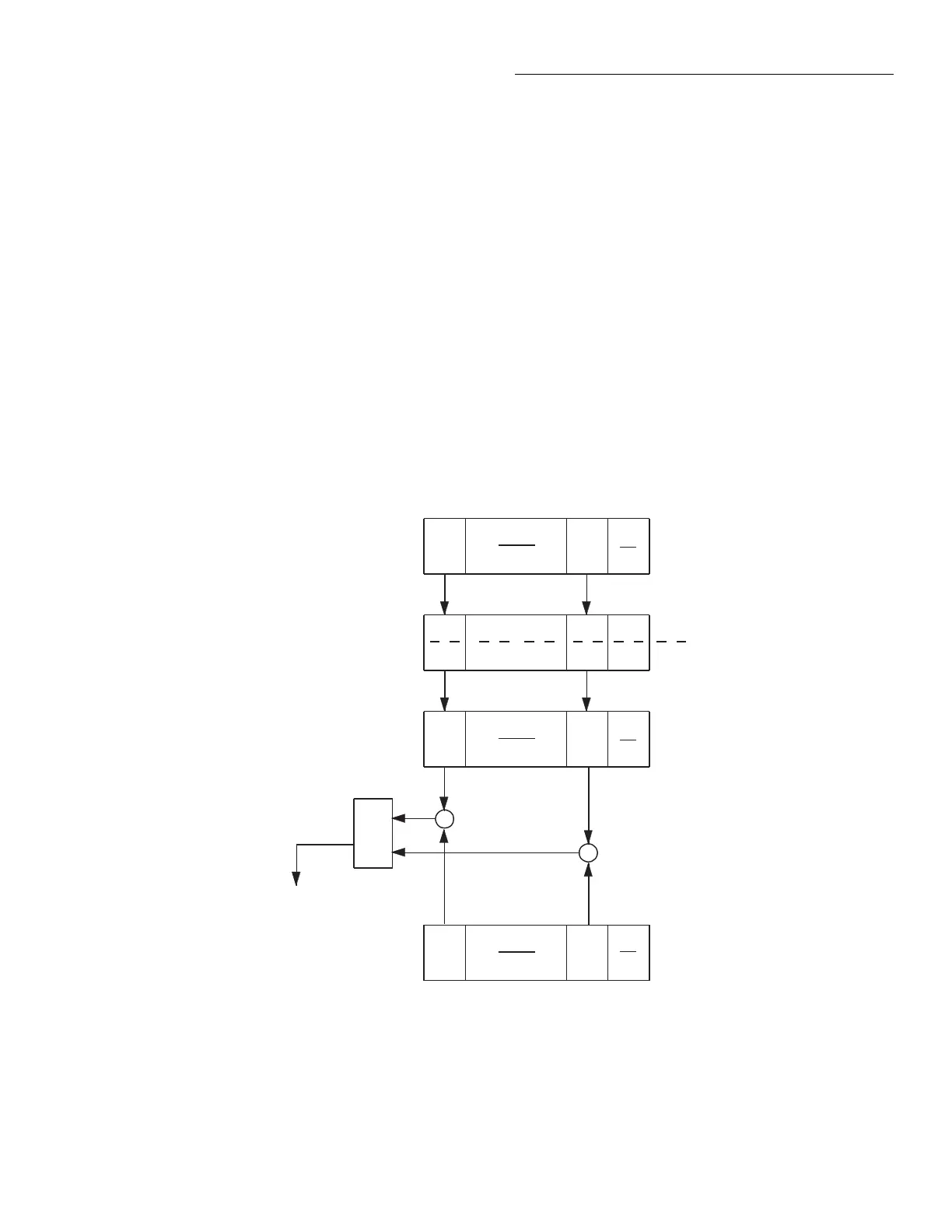
The reporting of the trigger event is controlled by a set of 16-
bit registers; the Trigger Condition Register, the Transition
Filter, the Trigger Event Register, and the Trigger Event En-
able Register. Figure 4-10 shows how these registers are
structured.
Bit B1 (Seq1) of the register set is used for the trigger event
(In trigger layer of Sequence 1). In general, Bit B1 sets when
the instrument is in (or has exited) the measure layer of op-
eration. An explanation of the Model 2001 operation process
is provided in paragraph 4.7. The various registers used for
trigger event status are described as follows. Note that these
registers are controlled by the :STATus:OPERation:TRIGger
commands of the :STATus subsystem (see paragraph 4.21).
Trigger Condition Register This is a real-time 16-bit
read-only register that constantly updates to reflect the trig-
ger layer status of the instrument. If bit B1 is set, the instru-
ment is in the trigger layer (measure layer) of operation.
The following SCPI query command can be used to read the
Trigger Condition Register:
:STATus:OPERation:TRIGger:CONDition?
The Trigger Condition Register and the Transition Filter are
used to set bit B1 of the Trigger Event Register. The Transi-
tion Filter is discussed next.
(B14 - B2)
(B15)
(B1) (B0)
OR
Trigger
Condition Register
Trigger Event
Enable Register
Seq 1 = Sequence 1 (Set bit indicates that the
2001 is in the trigger layer of Sequence 1)
& = Logical AND
OR = Logical OR
PTR = Positive Transition Register
NTR = Negative Transition Register
&
&
0
Seq1
(B14 - B2)
(B15)
(B1) (B0)
0
Seq1
(B14 - B2)
(B15)
(B1) (B0)
0
Always
Zero
Seq1
PTR
NTR
Trigger
Transition Filter
Trigger Event
Register
(B14 - B2)
(B15) (B1) (B0)
Seq1
To Waiting for Trigger
Bit (Trig) of Operation
Event Condition Register
(See Figure 4-7).
igure 4-10
Trigger event status

 Loading...


