IEEE-488 Reference
4-7
4.6.2 Operation event status
The reporting of operation events is controlled by a set of 16-
bit registers; the Operation Condition Register, the Transi-
tion Filter, the Operation Event Register, and the Operation
Event Enable Register. Figure 4-7 shows how these registers
are structured.
Notice in Figure 4-5 that bits B5 (Waiting in trigger layer)
and B6 (Waiting in an arm layer) of the Operation Condition
Register are controlled by the arm register set and the trigger
register set (see paragraphs 4.6.3 and 4.6.5 for details). Each
of the bits that is used in these registers represent an opera-
tion event. Descriptions of the operation event bits are pro-
vided in paragraph 4.21.
The operation status registers are controlled by the :STA-
Tus:OPERation commands in the :STATus subsystem (see
paragraph 4.21).
Operation Condition Register
This is a real-time 16-bit
read-only register that constantly updates to reflect the cur-
rent operating conditions of the Model 2001. For example,
while a calculation is being performed, bit B9 (Calc) of this
register will be set. At the completion of the calculation, bit
B9 will clear.
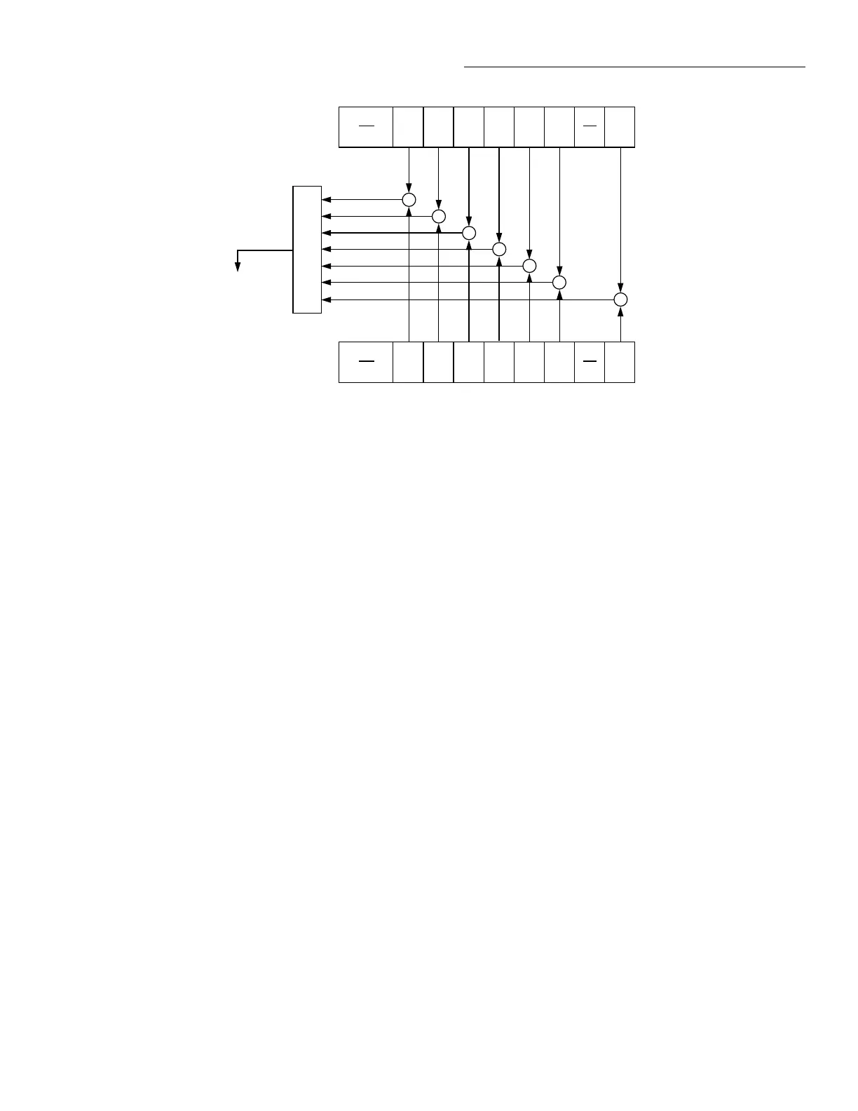
igure 4-6
Standard event status
* ESR ?
PON
(B7)
URQ
(B6)
CME
(B5)
EXE
(B4)
DDE
(B3)
QYE
(B2) (B1) (B0)
OR
Standard Event
Status Register
Standard Event
Status Enable
Register
PON = Power On
URQ = User Request
CME = Command Error
EXE = Execution Error
DDE = Device-Dependent Error
QYE = Query Error
OPC = Operation Complete
& = Logical AND
OR = Logical OR
&
&
&
&
&
OPC
&
&
PON
(B7)
URQ
(B6)
CME
(B5)
EXE
(B4)
DDE
(B3)
QYE
(B2) (B1) (B0)
OPC
* ESE
* ESE ?
To Event Summary
Bit (ESB) of
Status Byte
Register (See
Figure 4-13).
(B15 - B8)
(B15 - B8)
The following SCPI query command can be used to read the
Operation Condition Register:
:STATus:OPERation:CONDition?
The Operation Condition Register and the Transition Filter
are used to set the bits of the Operation Event Register. The
Transition Filter is discussed next.
Operation Transition Filter
The transition filter is made
up of two 16-bit registers that are programmed by the user. It
is used to specify which transition (0 to 1, or 1 to 0) in the
Operation Condition Register will set the corresponding bit
in the Operation Event Register.
The filter can be programmed for positive transitions (PTR),
negative transitions (NTR) or both. When an event bit is pro-
grammed for a positive transition, the event bit in the Opera-
tion Event Register will set when the corresponding bit in the
Operation Event Condition Register changes from 0 to 1.
Conversely, when programmed for a negative transition, the
bit in the status register will set when the corresponding bit
in the condition register changes from 1 to 0.

 Loading...


