Front Panel Operation
3-35
3.4.3 Two and four-wire resistance
2-wire resistance measurements
The Model 2001 can make 2-wire resistance measurements
between 1µΩ and 1.05GΩ. Assuming “bench reset” condi-
tions (see paragraph 3.12.1), the basic procedure is as fol-
lows:
1. Connect test leads to the INPUT HI and LO terminals of
the Model 2001. Either the front or rear inputs can be
used; place the INPUTS button in the appropriate posi-
tion.
2. Select the Ω2 function.
3. Select a range consistent with the expected resistance.
For automatic range selection, press the AUTO key. The
AUTO annunciator denotes whether auto-ranging is en-
abled.
4. Enable offset compensation if needed (refer to the pro-
cedure later in this paragraph).
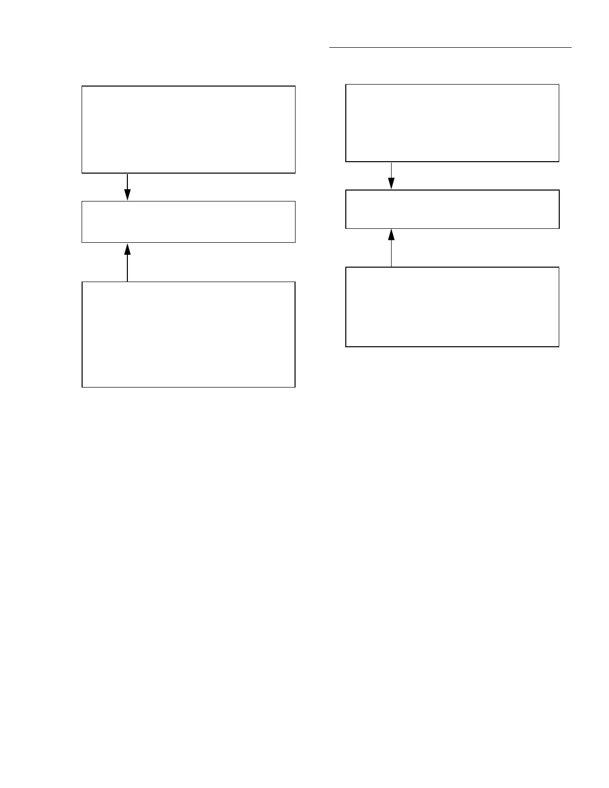
igure 3-13
C current multifuncton multiple displays
RMS (or AVG)
RANGE = Set by ACI range (auto or fixed).
Autoranges independently of other function.
REL = Operates normally.
SPEED = Set by ACI speed.
FILTER = Set by ACI filter.
RESOLUTION = Set by ACI resolution.
COUPLING = Set by ACI coupling.
AC-TYPE = Set by ACI AC-Type.
FREQ
RANGE = Set by MAX-SIGNAL-LEVEL in CONFIGURE
FREQUENCY menu.
Autorange has no effect.
REL = No effect.
TRIGGER LEVEL = Set while in FREQ. Not available in
CONFIGURE FREQUENCY menu.
FILTER = Unaffected by ACI filter. FREQ has no filter.
RESOLUTION = Fixed at 5 digits.
COUPLING = Set by ACI coupling.
INPUT TERMINALS = Fixed on CURRENT
+000.000 µAAC RMS (or AVG)
+0.0000 Hz
A. AC RMS (or average) current and frequency functions
B. AC RMS and average current functions
RMS
RANGE = Set by ACI range (auto or fixed).
Autoranges independently of other function.
REL = Operates normally.
SPEED = Set by ACI speed.
FILTER = Set by ACI filter.
RESOLUTION = Set by ACI resolution.
COUPLING = Set by ACI coupling.
AVG
RANGE = Set by ACI range (auto or fixed).
Autoranges independently of other function.
REL = No effect.
SPEED = Set by ACI speed.
FILTER = Unaffected by ACI filter.
RESOLUTION = Fixed at 5.5 digits.
COUPLING = Set by ACI coupling.
+000.000 µAAC RMS
AVG=000.000 µAAC
NOTE
Whether or not offset compensation is be-
ing used, the 20Ω, 200Ω, 2kΩ, 20kΩ, and
200kΩ ranges require zero correction in
order to achieve the best accuracy. The
zero correction procedure is located in a
following paragraph.
5. Connect the test leads to the resistance as shown in Fig-
ure 3-14.
CAUTION
Do not exceed 1100V peak between IN-
PUT HI and LO, or instrument damage
may occur.

 Loading...


