Front Panel Operation
3-33
MEASUREMENT-MODE
This option selects the DC current measurement mode, ei-
ther normal or in-circuit measurements. It is programmed as
follows:
1. From the CONFIGURE DCI menu, select
MEASUREMENT-MODE and press ENTER. The
following menu is shown:
DCI MEASUREMENT MODE
NORMAL IN-CIRCUIT
2. Highlight the desired mode and press ENTER.
NORMAL:
This option is for normal current measuring,
where the meter is placed in series with the current path and
the voltage across an internal shunt resistor is measured. The
specifications are derated by 50ppm for currents over 0.5A
because of the self-heating effects on the shunt resistor.
IN-CIRCUIT:
In-circuit current is a calculation based on a
4-wire resistance measurement and a voltage measurement.
It is similar to an offset-compensated ohms reading.
A measurement overflow occurs for any of the following
conditions:
• The measured voltage exceeds |±200mV|.
• The trace resistance is less than 1m
Ω
or greater than
10
Ω
.
• The in-circuit current is greater than 12A.
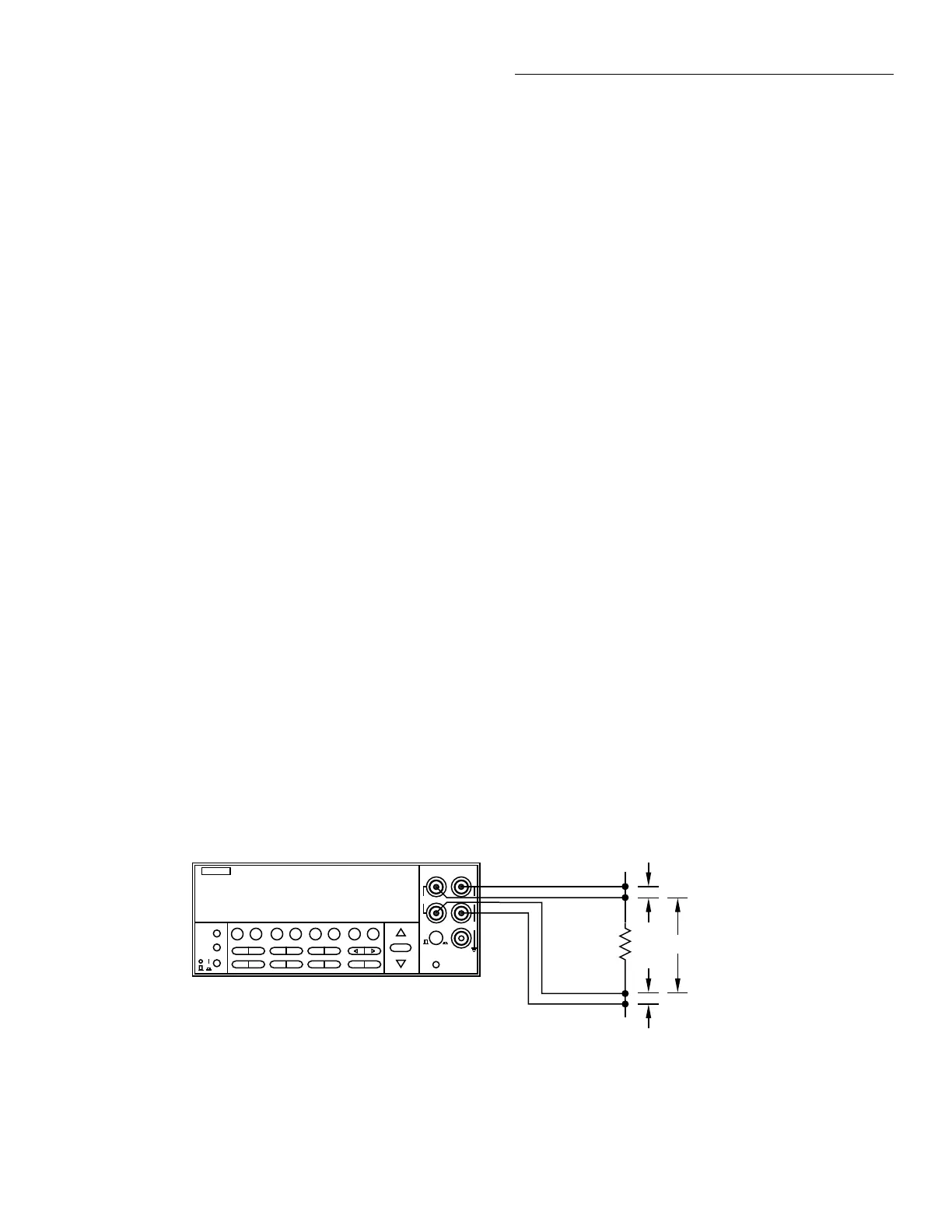
The current in a low resistance conductor (e.g., a printed cir-
cuit trace) can be measured without breaking the current
path. The Model 2001 can do this with a pair of Kelvin test
probes across the conductor. See Figure 3-12. The method
follows:
Figure 3-12
DC in-circuit current measurements
NEXT
DISPLAY
PREV
POWER
DCV ACV DCI ACI Ω2 Ω4
FREQ TEMP
REL TRIG STORE RECALL
INFO LOCAL CHAN SCAN CONFIG MENU EXIT ENTER
RANGE
AUTO
FILTER MATH
RANGE
2001 MULTIMETER
SENSE
Ω 4 WIRE
HI
INPUT
LO
INPUTS
CAL
500V
PEAK
F
R
FRONT/REAR
2A 250V
AMPS
350V
PEAK
1100V
PEAK
Model 2001
Circuit
Under Test
Caution : Maximum Input = +200mV on (I
IN - CKT
+ I
SOURCE
) • R
TRACE
,
where I
SOURCE
= 10mA.
+00.207 ADC ICkt
Trace resistance: 1.0000Ω
Y
Y
x
Note: The distance
"X" must be greater
than 10 times the
distance "Y" or
additional errors will
be introduced.
1. Using one set of the Kelvin probe tips, the instrument
sources a known current (I
SOURCE
) through the conductor
and simultaneously measures the resulting voltage
(V
MEAS1
) with the other set of probe tips:
or
2. The instrument then measures the voltage (V
MEAS2
)
across the conductor without sourcing an additional cur-
rent:
or
3. It then calculates the in-circuit current by combining the
equations and solving for I
IN-CKT
:
V
MEAS1
I
IN-CKT
I
SOURCE
+()R
TRACE
=
R
TRACE
V
MEAS1
I
IN-CKT
I
SOURCE
+()
--------------------------------------------------=
R
TRACE
V
MEAS2
I
IN-CKT
()
-----------------------=
V
MEAS1
I
IN-CKT
I
SOURCE
+()
--------------------------------------------------
V
MEAS2
I
IN-CKT
()
-----------------------=
V
MEAS1
I
IN-CKT
()V
MEAS2
I
IN-CKT
I
SOURCE
+()=
V
MEAS1
I
IN-CKT
()-V
MEAS2
I
IN-CKT
()V
MEAS2
I
SOURCE
()=
I
IN-CKT
V
MEAS1
-V
MEAS2
()=V
MEAS2
I
SOURCE
()
I
IN-CKT
V
MEAS2
I
SOURCE
()
V
MEAS1
-V
MEAS2
()
----------------------------------------------=

 Loading...


