IEEE-488 Reference
4-15
4.6.6 Measurement event status
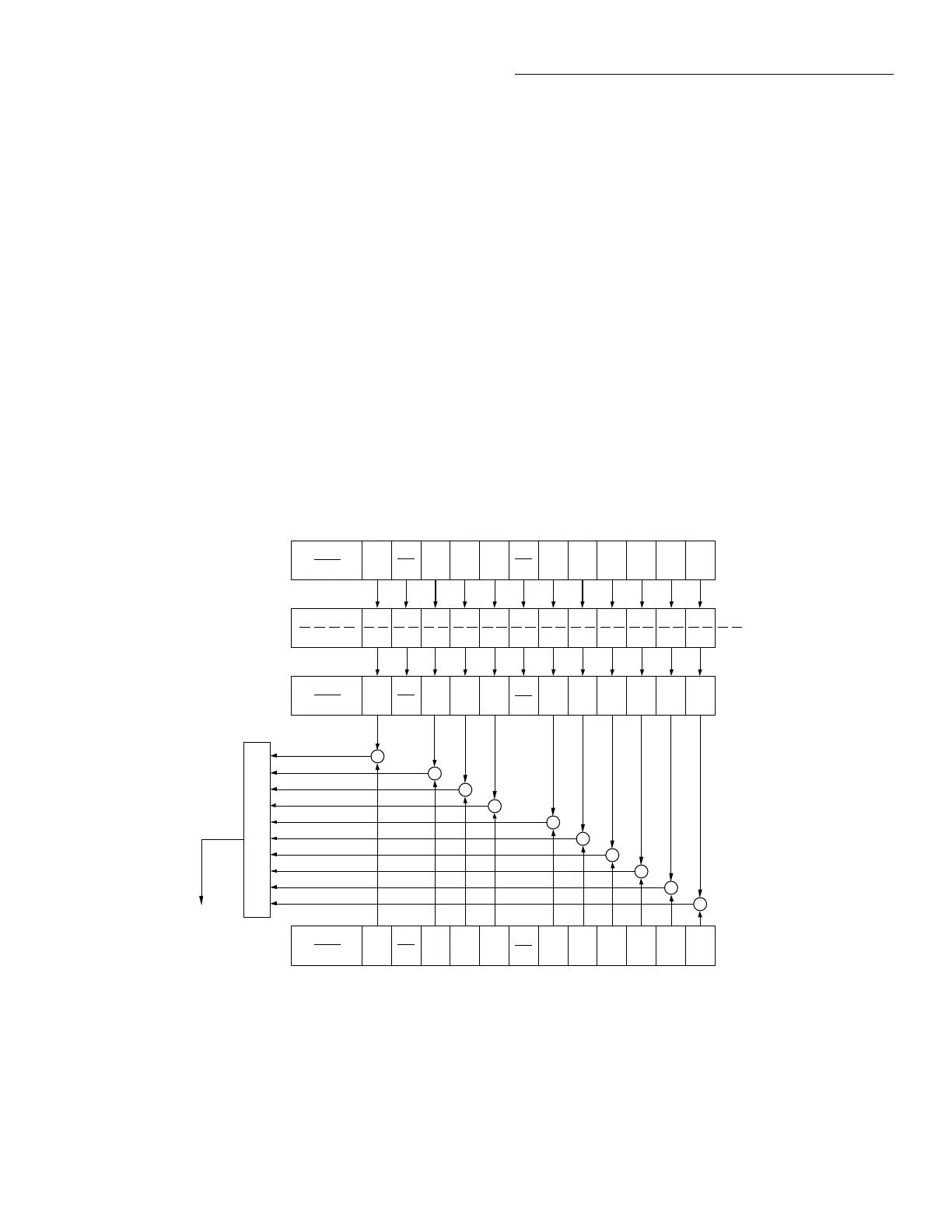
The reporting of measurement events is controlled by a set of
16-bit registers; the Measurement Event Condition Register,
the Transition Filter, the Measurement Event Status Register
and the Measurement Event Enable Register. Figure 4-11
shows how these registers are structured. Each of the bits that
is used in these registers represent a measurement event.
Descriptions of the measurement event bits are provided in
paragraph 4.21.
The measurement status registers are controlled by the
:STATus:MEASurement commands in the :STATus
subsystem (see paragraph 4.21).
Measurement Condition Register This is a real-time 16-
bit read-only register that constantly updates to reflect the
current operating conditions of the Model 2001. For exam-
ple, when the trace buffer becomes full, bit B9 (BFL) of this
register will be set. When the buffer is not full, bit B9 will
clear.
igure 4-11
easurement event status
(B15 - B12) (B10) (B9) (B8) (B7) (B6)
RAV
(B5) (B4) (B3)
OR
BFL = Buffer Full
BHF = Buffer Half Full
BAV = Buffer Available
& = Logical AND
OR = Logical OR
(B2)
LL1
(B1) (B0)
(B15 - B12) (B10) (B9)
BHF
(B8)
BAV
(B7) (B6)
RAV
(B5) (B4) (B3) (B2)
LL1
(B1) (B0)
Measurement Event
Register
(B15 - B12)
Measurement Event
Enable
Register
To Measurement
Summary Bit
(MSB) of Status
Byte Register.
(See Figure 4-13)
&
&
PTR = Positive Transition Filter
NTR = Negative Transition Filter
PTR Measurement
NTR Transition Filter
(B15 - B12) (B10) (B9) (B8) (B7) (B6)
RAV
(B5) (B4) (B3)
(B2)
LL1
(B1) (B0)
Measurement
Condition Register
BFL HL2 HL1 ROF
BFL HL2 HL1 ROF
BFL HL2 ROF
&
&
&
&
BHF BAV LL2
BHF BAV LL2
LL2 HL1
&
&
&
(B10) (B9)
BHF
(B8)
BAV
(B7) (B6)
RAV
(B5) (B4) (B3) (B2)
LL1
(B1) (B0)
BFL HL2 ROFLL2 HL1
RAV = Reading Available
HL2 = High Limit 2
LL2 = Low Limit 2
HL1 = High Limit 1
LL1 = Low Limit 1
ROF = Reading Overflow
BPT
(B11)
BPT
(B11)
BPT
(B11)
&
BPT
(B11)
BPT = Buffer Pretriggered
The following SCPI query command can be used to read the
Measurement Condition Register:
:STATus:MEASurement:CONDition?
The Measurement Condition Register and the Transition Fil-
ter are used to set the bits of the Measurement Event Regis-
ter. The Transition Filter is discussed next.
Measurement Transition Filter The transition filter is
made up of two 16-bit registers that are programmed by the
user. It is used to specify which transition (0 to 1, or 1 to 0)
in the Measurement Condition Register will set the corre-
sponding bit in the Measurement Event Register.
The filter can be programmed for positive transitions (PTR),
negative transitions (NTR) or both. When an event bit is pro-
grammed for a positive transition, the event bit in the Mea-
surement Event Register will set when the corresponding bit
in the Measurement Condition Register changes from 0 to 1.
Conversely, when programmed for a negative transition, the

 Loading...


