75
FUSES AND RELAYS
3.4 FUSES AND RELAYS
3.4.1 FUSES
3.4.1.1 EQUIPMENT FUSES
POSITION COLOUR CAPACITY (A) INVOLVED CIRCUIT
1 Green 30 Engine stop
2 Violet 3 Engine accosting alarm, start relay, instrument power supply
3 Light blue 15 Fan
4 Red 10 Arrangement for radio set installation
5 Brown 7,5 Revolving light, servocontrol solenoid valve
6 Red 10 Fuel pump, horn, TBG
7 Brown 7,5 Hammer solenoid valve
8 Brown 7,5 Outlet, cab
9 Brown 7,5 Alternator, speed increase solenoid valve
10 Brown 7,5 Engine stop solenoid
11 Brown 7,5 Working light
• When changing a fuse, make sure that the ignition key is in position «».
• If the fuses are oxidized, corroded or do not fit perfectly in their seat, replace them only with new fuses
having the same capacity.
• If the engine does not run when the ignition switch is turned to position ( ) (START), check the main
fuse and if necessary change it.
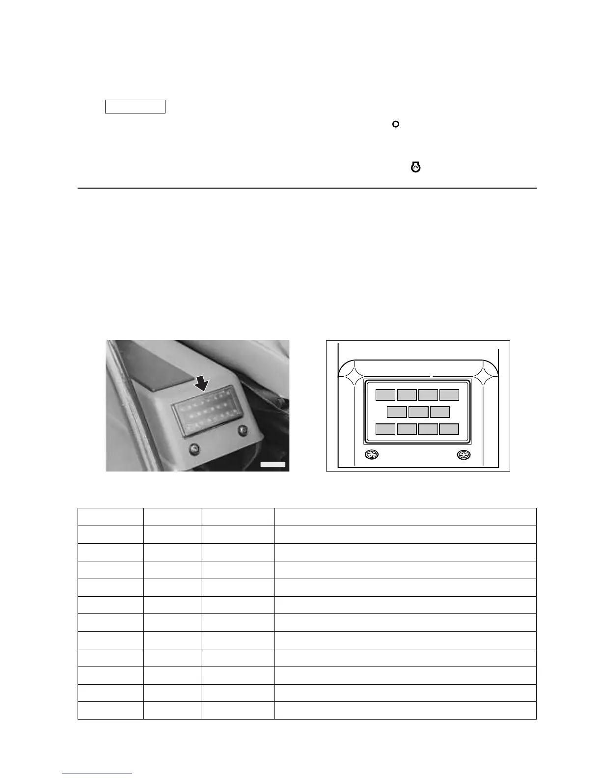
The equipment fuses are grouped on a single base positioned on the left control box, while the main fuse is posi-
tioned inside the battery compartment.
RWAA0880
1
2
3
4
5
67
8
9
10
11
RWA10030
 Loading...