Chapter 5 Disassembly and Assembly
5-54
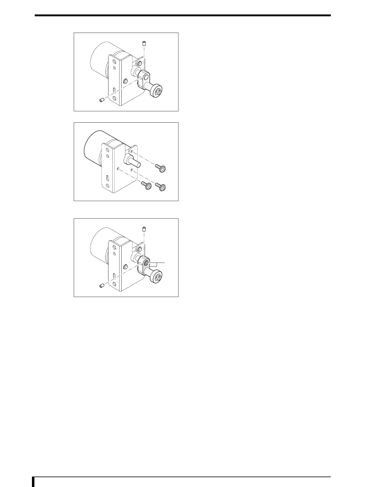
4 Remove the cam unit assembly.
•
2 setscrews
5 Remove the Lock Motor.
•
3 screws (M3 x 6)
6 Install the new Lock Motor on the motor mount
board.
•
3 screws (M3 x 6)
7 Install the cam unit assembly.
•
2 setscrews
Fix the gear, aligning the Surface A in the figure.
8 Install the lock release motor that was removed in
Step 3.
•
2 screws (M4 x 8)
9 Connect the connector (JP16) that was removed
in Step 2.
10 See " Installation Procedures (Page 5-8)" in "5.2.3 Removing/Installing the Exterior Panel
and Insertion Unit" to install the first front panel.
Now, you have finished with the procedures to replace the Lock Motor.
A
 Loading...