Chapter 5 Disassembly and Assembly
5-75
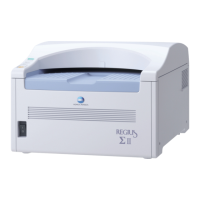
4 Remove the connector and the grounding cable
from the optical unit.
•
LMC
• CN1 (ACN1: cable)
• CN2 (ACN2: cable)
• CN9 (ACN9: cable)
• Eraser unit junction cable
• JJ61 (JP61: cable)
• Grounding cable
5 Remove the snap ties and other parts.
•
Snap ties at 3 locations
• A: wiring band at a location (cut it off)
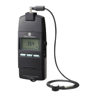
6 Remove the connector (CN11) from the CIU.
•
CN11 (CCN11: cable)
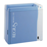
7 Cut off the wiring band (5 locations) retaining the
cable removed in Step 6.
When installing, position the white mark on the cable to
the position A in the figure. In addition, when fixing,
make sure that the cable is located outside at the
positions A, B, D and E.
Grounding cable
JP61
A
CN2
CN1
CN9
Second
Front Back Side
Caution
When removing the connector, hold a notch
on the connector without pulling a cable.
Giving a strong pull to the cable may cause
it to be broken.
First Front Back Side
CN11
Caution
When removing the connector, hold a notch
on the connector without pulling a cable.
Giving a strong pull to the cable may cause
it to be broken.
Second Front Back Side
 Loading...