3-POINT HITCH & DRAWBAR82
3-POINT HITCH
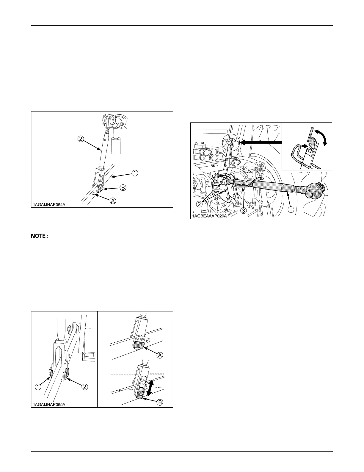
BSelecting the holes of Lower Links
There are 2 holes in the lower links. For most operations
the lifting rods should be attached to the (B) hole.
A The lifting rods may be attached to (A) for greater
lifting force.
BAdjusting Lateral Float
To allow the implement to follow ground contour, attach
the rectangular washers and pin heads in vertical position.
To hold the implement, reset the rectangular washers and
pin heads in horizontal position.
C Floating mechanism
When the floating mechanism is used, the implement is
able to follow the tractor freely in response to the soil and
ground conditions. This is suited for operation with
implements wider than the tractor.
BSelecting the Top Link Mounting Holes
Select the proper set of holes by referring to the
"Hydraulic Control Unit Use Reference Chart" in
"HYDRAULIC UNIT" section.
BDrawbar
Remove the drawbar if a close mounted implement is
attached.
1. Make preparations for attaching
implement.
(1) Lower link
(2) Lifting rod
holes: (A), (B)
(1) Rectangular washer
(2) Pin head
(A) Horizontal position
(B) Vertical position
(1) Top link
(2) Mounting hole
(3) Handle
 Loading...