Lenze · Decentralised frequency inverter 8400 motec (EtherNet/IP™ option) · EDS84DMOTEIP EN 3.0 - 02/2019 51
I/O data transfer (implicit messages)
I/O assemblies
_ _ _ _ _ _ _ _ _ _ _ _ _ _ _ _ _ _ _ _ _ _ _ _ _ _ _ _ _ _ _ _ _ _ _ _ _ _ _ _ _ _ _ _ _ _ _ _ _ _ _ _ _ _ _ _ _ _ _ _ _ _ _ _
8.4 I/O assemblies
The Communication Unit supports the Assembly Object (4 / 0x04) ( 114) and the "AC Drive Profile"
objects ( 133).
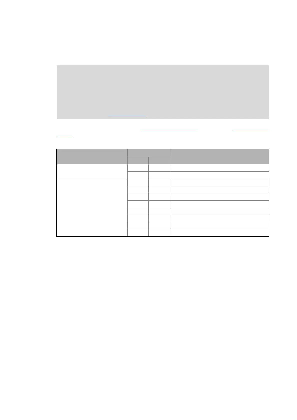
For data exchange, the Communication Unit supports the following assembly object instances:
Assembly output objects (outputs) are usually used for controlling the enable/disable state of the
inverter and for supplying the speed or torque references.
Assembly input objects (inputs) are usually used to monitor the drive status and the runtime values
such as actual speed, current, actual position and position error.
Depending on the data length defined by the scanner, the memory map of the I/O data can have
different sizes.
Note!
The terms "input" and "output" refer to the point of view of the scanner:
• Assembly input objects (input) are sent from the adapter to the scanner.
• Assembly output objects (output) are sent from the scanner to the adapter.
The length of the I/O data must correspond with the respective resulting length of the
mapped ports (I/O data mapping
( 48)).
Application Instance ID Assembly object instance
[dec] [hex]
Lenze technology applications / user-
definable parameter sets
110 0x6E Custom Output
111 0x6F Custom Input
"AC Drive Profile" application 20 0x14 Basic Speed Control Output
21 0x15 Extended Speed Control Output
22 0x16 Speed and Torque Control Output
23 0x17 Extended Speed and Torque Control Output
70 0x46 Basic Speed Control Input
71 0x47 Extended Speed Control Input
72 0x48 Speed and Torque Control Input
73 0x49 Extended Speed and Torque Control Input
 Loading...