Grove Published 01-29-2015, Control # 512-01 3-13
TMS700E SERVICE MANUAL ELECTRIC SYSTEM
Table 3-13
4. Repair is straightforward.
a. ALARM: check or replace fuse, or replace faulty
alarm or faulty sensor (switch, relay, sending unit),
install new alarm or sensor, test alarm.
b. INDICATOR: check and/or replace fuse, or remove
faulty light or faulty sensor (switch, relay, sending
unit), install new light or sensor, test indicator.
c. BACKUP LIGHT: check and/or replace fuse, or
remove faulty relay, light, or faulty sensor (electric
shifter), install new light or sensor, test lights.
d. HORN: check and/or replace fuse or remove faulty
horn or faulty trigger (switch, relay), install new horn
or trigger, test horn.
e. BUZZER: check and/or replace fuse or remove
buzzer, install new buzzer, test buzzer.
Troubleshooting Crane Components and
Accessories
1. If a crane component or accessory won’t work when it is
supposed to, check and/or replace fuse. Also check and
replace its relay as needed.
2. Check the component or accessory, its control or
triggering component, and its circuit for continuity
problems and other problems. Repair any faulty
component or accessory or trigger. Repair wiring if
faulty.
Carrier
The following carrier circuit designs apply (Table 3-14)
(connecting wiring and passage through swivel slip ring -- as
applicable -- is understood):
Table 3-14
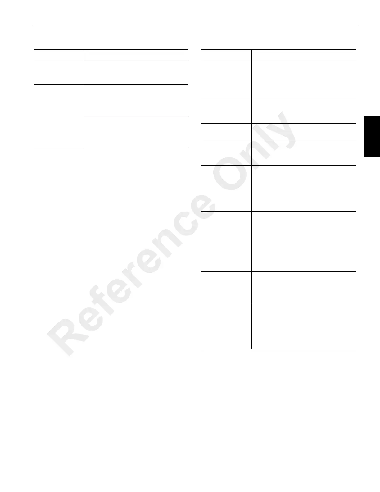
Superstructure
The following superstructure circuit designs apply (Table 3-
15) (connecting wiring and passage through swivel slip ring -
- as applicable -- is understood):
Component Circuit
Swing Horn
F4 to horn relay (K4) coil to horn
switch to ground. Parallel branch from
horn relay contacts to horn to ground
Center Front
Jack
Overloaded
Indicator
F9 to indicator to normally open
pressure switch on cylinder to ground
Engine Stop
Indicator
(F9 to indicator) and (F2 in carrier to
power select relay (K104) contacts to
superstructure ignition switch to
buzzer) to engine ECM
Component Circuit
Windshield
Wiper Motor
and Windshield
Washer Pump
Motor
F7, wiper/washer switch, motors in
parallel, grounds
Heater Fan
F16, heater switch, fan motor,
ground. Parallel circuit to LED
indicator in switch to ground
Cab Circulating
Fan
F8, switch, motor, ground
Defroster Fan
F17, defrost switch, motor, ground.
Parallel circuit to LED indicator in
switch to ground
Air Dryer Heater
F9 to air dryer relay (K107) contacts
to air dryer temperature switch, to
heating element to ground. Branch
circuit from carrier F5/superstructure
F9 to air dryer relay (K107) coil to
ground
Hydraulic Oil
Cooler Fan
Motor
Fuse F12 to hydraulic oil cooler relay
(K103) contacts to fan motor to
ground. Branch circuit from
superstructure ignition switch to
superstructure ignition relay (K3)
contacts to oil cooler temperature
switch contacts to relay (K103) coil to
ground
Outrigger
Enable Circuit
Carrier F5/superstructure F9 to
outrigger enable relay (K105) coil to
park brake on indicator circuit
pressure switch contacts to ground
Outrigger
Control
functions
F3 to outrigger enable relay (K105)
contacts to selector switches in
superstructure control box or carrier
optional remote mounted control
boxes extend/retract switches to
engine ECM for throttle control
Reference Only

 Loading...


