Grove Published 01-29-2015, Control # 512-01 8-37
TMS700E SERVICE MANUAL UNDERCARRIAGE
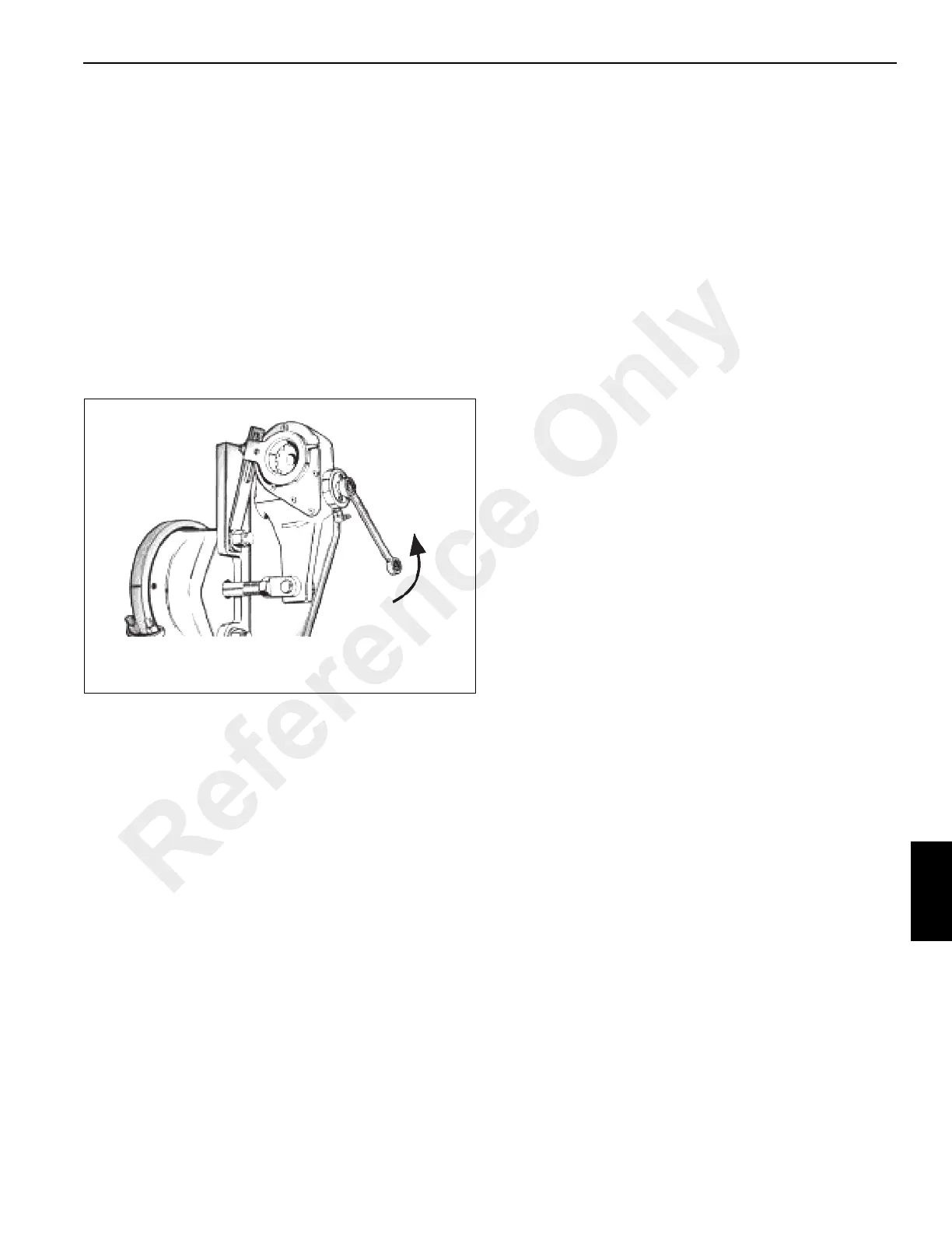
5. Using a pry bar, move the slack adjuster so that the
linings contact the drum. Measure the distance between
the same points as in step 4. This dimension is “Y” in
(Figure 8-38).
6. Subtract dimension “X” from dimension “Y”. The
difference should be 12.7 to 15.9 mm (0.5 to 0.625 in). If
the stroke falls within these limits, no adjustment is
required. If it falls outside these limits, proceed to step 7.
7. Rotate the adjusting hex approximately 1/8 turn in the
direction required and re-measure the stroke. Continue
this process until the stroke is within limits. A minimum of
17.6 Nm (13 lb-ft) of torque is required to turn the hex
and overcome the internal clutch. A ratcheting noise will
be heard. Do not use an impact wrench or internal
damage will occur (Figure 8-39).
8. With brakes released, check installation indicator
Figure 8-38 and Figure 8-39 to determine proper
adjustment.
9. If installation indicator is not positioned properly, refer to
Figure 8-39. Loosen fastener holding indicator to anchor
bracket, rotate indicator as required and retighten
fastener.
10. Uncage spring brake if so equipped.
REAR BRAKES
Description
Brakes
The rear brakes are air actuated and cam operated. Each
shoe, which is steel fabricated, employs two 19 mm (0.75 in)
tapered block liners. The shoes are mounted on individual
anchor pins and supported by open type spiders. Automatic
slack adjusters maintain proper adjustment of the push rod
stroke and lining to drum clearance.
The brake actuator is a conventional brake air chamber with
an emergency (parking) brake spring mechanism
incorporated into the air brake chamber. The brake chamber
has an aluminum body and pressure plate with a steel non-
pressure plate that houses a service/emergency diaphragm,
piston, and two springs.
Spring Brake Actuator
The spring brake actuator, which is the upper part of the air
brake chamber, is spring applied and air released. When an
air pressure of 4.82 bar (70 psi) or more is applied against
the piston, the spring is compressed and braking is done with
the service brakes. When the air pressure is removed, the
spring pushes against the piston and diaphragm plate to
apply the brake. Internal venting works in conjunction with a
one-way breather cap that allows system air to fill the
vacuum behind the piston to keep out atmospheric air and
contamination. The unit is equipped with a manual caging
bolt to permit safe handling and service work.
Reference Only

 Loading...


