BOOM TMS700E SERVICE MANUAL
4-18 Published 01-29-2015, Control # 512-01
Removal and Installation
Removal and installation of the telescope cylinder from the
boom is described under disassembly and assembly of the
boom. Refer to Maintenance, page 4-2.
Disassembly and Assembly
Disassembly and assembly procedures of the telescope
cylinder and control valve are provided in Hydraulic System,
page 2-1 under Cylinders and Valves respectively.
LIFT CIRCUIT
Description
The boom lift circuit consists of the lift hydraulic remote
controller, lift directional control valve, holding valve, and the
lift cylinder. These components enable the boom to be raised
or lowered to various degrees of elevation ranging from -3 to
+78 degrees from horizontal.
The lift directional control valve is the closed spool type and
is described under Valves, page 2-19.
Refer to Hydraulic Remote Control Valve, page 2-34 for a
complete description of the hydraulic remote controller.
The lift cylinder has a 30.48 cm (12.0 in) bore and is the
double acting type. Dirt and other foreign material is
prevented from entering the cylinder and causing internal
damage by a wiper seal during rod retraction. Oil Seals on
both the piston and cylinder head prevent internal and
external hydraulic oil leakage. Refer to Lift Cylinder, page 2-
54 for a complete description of the lift cylinder.
The holding valve is a balanced poppet type hydraulic valve.
It is threaded into the port block which is an integral portion of
the lift cylinder barrel. The holding valve functions when
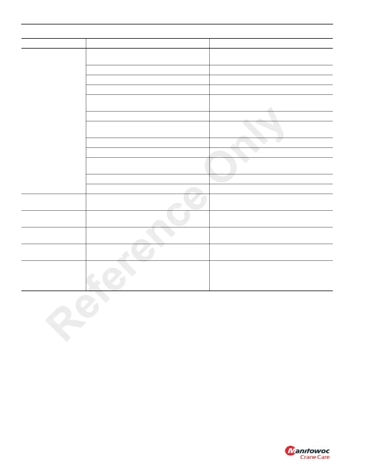
4. Telescope cylinder
will not retract.
a. Low hydraulic oil level. a. Check for leaks. Repair any found.
Replenish oil to proper level.
b. Relief valve damaged. b. Repair or replace relief valve.
c. Excessive load. c. Reduce load. (Refer to load chart).
d. Inoperative check valve. d. Replace check valve.
e. Clogged hose and fittings. e. Replace hose or fittings. (Refer to
Grove Parts Manual).
f. Broken valve spool. f. Replace valve section.
g. Broken piston(s). g. Replace piston(s) and all cylinder
seals.
h. Damaged piston seals. h. Replace all cylinder seals.
i. Bent boom section(s). i. Replace damaged boom section(s).
j. Broken hydraulic pump coupling. j. Replace broken hydraulic pump
coupling.
k. Worn or damaged hydraulic pump. k. Repair or replace pump.
l. Broken hydraulic pump shaft. l. Replace pump shaft.
5. Section 2 will not
extend.
a. Right side check valve blocked. a. Readjust, repair, or replace valve.
6. Section 2 will not
retract.
a. Right side check valve closed. a. Readjust valve
7. Section 3 will not
extend.
a. Left side check valve is closed a. Readjust valve
8. Section 2 retracts
before Section 3.
a. Right side
check valv
e is open or
hosed backwards.
a. Install hoses properly
9. Section 3 extends
only a short
distance, then
stops.
a. Left check valve is open or hosed
backwards
a. Install hoses properly.
SYMPTOM PROBABLE CAUSE SOLUTION
Reference Only

 Loading...


