UNDERCARRIAGE TMS700E SERVICE MANUAL
8-44 Published 01-29-2015, Control # 512-01
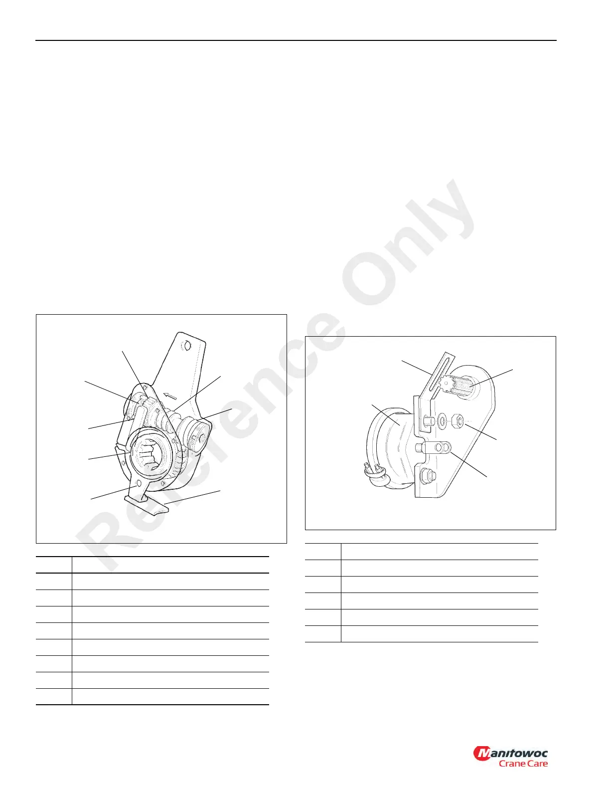
AUTOMATIC SLACK ADJUSTER
Description
The automatic slack adjuster (see Figure 8-50)
compensates for normal wear in the brake shoe linings by
maintaining a nominal clearance between the lining and
drum. The clearance notch in the rack corresponds to the
normal lining-to-drum clearance.
When the brake is applied the rack moves upward and
rotates the one way clutch to allow for slippage in this
direction. Brake application torque presses the wormshaft
against the coil spring which releases the cone clutch.
When the brake is released, the coil spring presses against
the wormshaft and engages the cone clutch which pulls the
rack back to its original position in the clearance notch.
Lining wear causes the rack to turn the locked one-way
clutch while rotating the wormshaft via the locked cone
clutch. The wormshaft rotates the wormwheel and camshaft,
which adjusts the brakes.
Maintenance
Removal
NOTE: See Figure 8-51 for steps 1 through 5.
1. Remove the cotter pin and clevis pin from the push rod
clevis.
2. Loosen the anchor bracket hardware.
3. Turn the adjuster nut until the slack adjuster is clear of
the air chamber pushrod clevis.
4. Remove the snap ring and outer shim washer(s) from
the camshaft.
5. Remove the slack adjuster with a suitable puller.
Installation
NOTE: See Figure 8-51 for steps 1 through 3.
1. Verify that the pushrod is fully retracted.
2. Install the anchor bracket loosely. Do not tighten the
anchor bracket fasteners at this time.
3. Apply anti-seize type lubricant to the camshaft splines.
Install the slack adjuster onto the camshaft with the
adjusting hex pointing away from the air brake chamber.
Secure with outer shim washer(s) and snap ring.
Item Description
1 Cone CLutch
2 One-Way Clutch
3 Wormshaft
4 Coil Spring
5 Control Arm Anchor
6 Control Arm
7 Clearance Notch
8Rack
Item Description
1 Air Chamber
2 Anchor Bracket
3 Camshaft
4 Mounting Nut
5 Clevis and Push Rod
Reference Only

 Loading...


