Grove Published 01-29-2015, Control # 512-01 6-13
TMS700E SERVICE MANUAL SWING SYSTEM
3. Using an appropriate lifting device, align the
superstructure over the carrier in the travel position and
carefully lower the superstructure, being careful not to
damage the swivel assembly, into position on the carrier
bearing plate.
NOTE: It will be necessary to rotate the superstructure
while attached to the lifting device. Outer race bolts
can only be installed from the front or from under
the cab.
4. Install 40 new bolts and washers. Refer to Outer Race
Torquing, page 6-10.
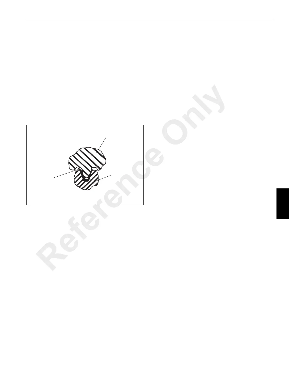
NOTE: If a new bearing is being installed, a new pinion
gear must also be used. Align the high point
(maximum eccentricity) on the bearing with the
new pinion gear high point (see Figure 6-4).
5. Install the gearbox pinion aligning the high point
(maximum eccentricity) on the turntable bearing. Using
a 0.203 mm (0.008 in) thick shim, check the backlash
(see figure). If the pinion must be moved to achieve
proper backlash, contact your distributor.
6. Position the two retainer plates on the bottom of
hydraulic swivel spool, engaging the lugs on the carrier
frame, and secure them to the spool with four bolt
retainers and eight bolts. Bend all the retainer tabs to
make contact with the bolt heads.
7. Plug the swivel wiring harness connectors into the
carrier receptacles. Secure the ground wire to the
ground stud using a washer, lockwasher, and nut.
8. Install the clamp securing the swivel wiring harness to
the retainer plate on the bottom of the hydraulic swivel.
9. Connect all water and hydraulic lines to the ports on the
bottom of the swivel as tagged during removal.
10. Install the boom and lift cylinder following the procedures
outlined in Boom, page 4-1.
11. Reconnect the batteries.
12. Check the slew potentiometer in the electrical swivel for
proper orientation. Refer to Swivels in this section.
13. Install the counterweight. Refer to the Operator Manual.
Testing
Activate the crane and check for proper function.
NOTE: If the superstructure does not turn freely after
bearing and pinion replacement, contact your
distributor.
SWIVELS
Description
The swivel assembly (see Figure 6-5) consists of a 5 port
hydraulic swivel, a 2 port water swivel, and a 49 conductor
slip ring electrical swivel. Solid connections cannot be used
to transfer oil, heater hot water and electricity between the
carrier and superstructure due to the continuous 360 degree
swing. The use of swivels efficiently accomplishes this
function.
The barrel portion of the hydraulic swivel is attached to the
turntable base plate by four bolts, washers and bushings,
which connect to mounting lugs on the case. The spool
portion of the swivel rides upon a thrust ring at the top of the
swivel case. The spool portion is held stationary with the
carrier by bolts, and bolt retainer plates attached to the
swivel retainer plate which engages the carrier frame lugs
with bolts and jam nuts. This allows the spool to remain
stationary with the carrier as the case rotates with the
superstructure.
The spool portion of the water swivel is attached to the spool
of the hydraulic swivel by four bolts. The hydraulic and water
swivel spools remain stationary with the carrier as the
superstructure rotates. The water swivel case contains a lug
which is keyed to a corresponding lug on the hydraulic swivel
case, causing the water swivel to rotate with the
superstructure.
The electrical swivel center or collector ring assembly is
secured by setscrews to a center post which is bolted to the
spool of the hydraulic swivel. This allows the collector ring
assembly to remain stationary with the carrier. The outer
portion or brush assembly is mounted on two studs which
are located on the mounting plate assembly which is
retained to the water swivel barrel by a bolt. This allows the
brush assembly to rotate with the superstructure around the
stationary collector core.
Maximum Eccentricity Tooth
Shim
Pinion
FIGURE 6-4
Reference Only

 Loading...


