UNDERCARRIAGE TMS700E SERVICE MANUAL
8-34 Published 01-29-2015, Control # 512-01
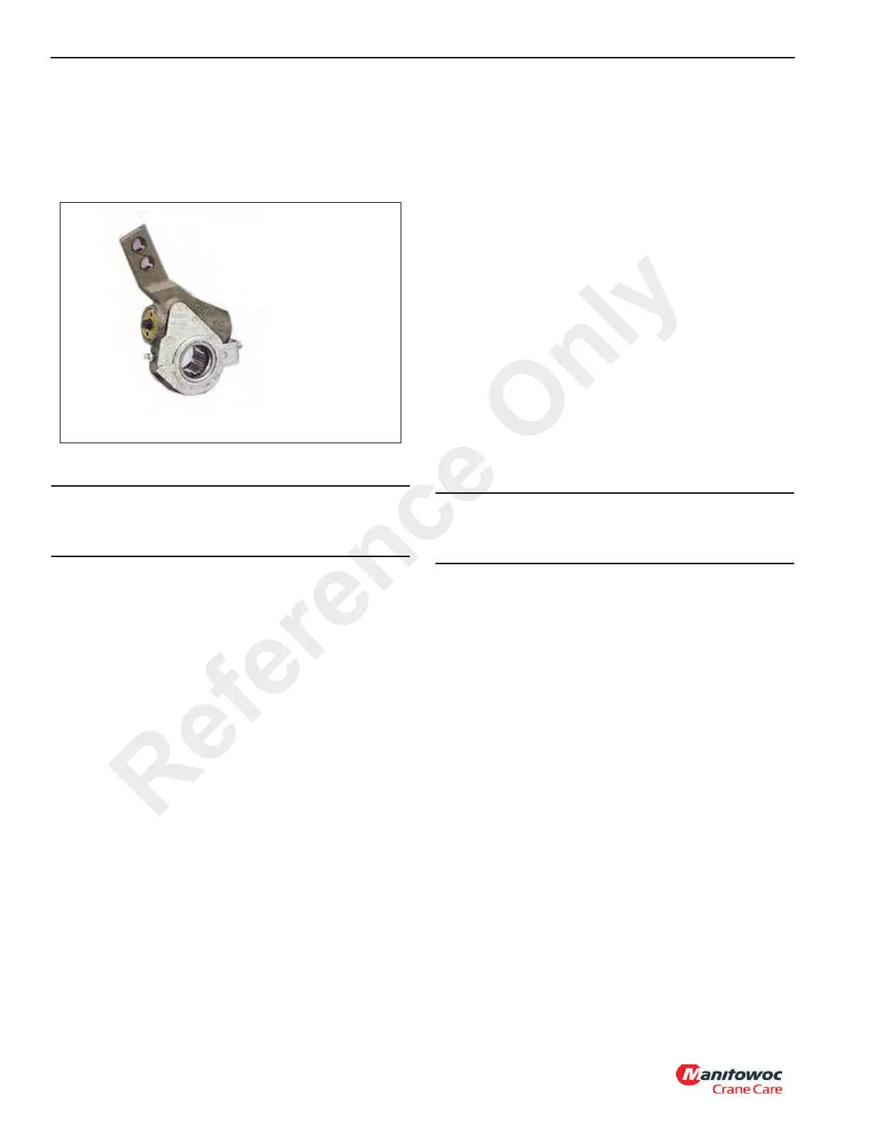
Alternative 2
NOTE: If your slack adjuster is as pictured in Figure 8-34,
use the removal, installation and adjustment
procedures that follow.
REMOVAL
1. Block wheels to prevent crane from moving. Ensure
system tank pressure is above 6.89 bar (100 psi).
2. Use a wrench to turn the manual adjusting nut
counterclockwise until the brake shoes are fully
retracted and the lining clears the drum.
NOTE: Note the orientation of the slack adjuster with
reference to the push rod before removal to assure
proper orientation at installation.
3. Remove the brake adjuster from the camshaft.
Installation
1. Block wheels to prevent crane from moving. Ensure
system tank pressure is above 6.89 bar (100 psi).
2. Check that the push rod is fully retracted and apply air to
release spring brake. If air is not available, spring brake
must be manually caged back.
3. Install anchor bracket loosely.
4. Do not tighten anchor bracket fasteners at this time.
5. Apply Anti-Seize type lubricant to camshaft splines.
6. Install the brake onto the camshaft with the adjusting hex
pointing away from the brake chamber.
NOTE: Do not pull push rod out to meet the brake adjuster.
7. Secure the brake adjuster on the camshaft. Use at least
one inner washer and enough outer washers to allow no
more than 1.5 mm (0.060 in) movement of adjuster on
camshaft.
8. Rotate the adjusting hex nut clockwise until the clevis
hole lines up with the brake adjuster arm hole.
9. Apply anti-seize to clevis pin. Install and secure with
cotter pin.
10. The control arm can be placed anywhere within the
range of the bracket slot for automatic adjustment to
take place. Rotate the control arm towards the axle until
they come to a complete stop and secure in that
position.
11. Tighten all anchor bracket fasteners.
12. Rotate the adjusting hex clockwise until the lining lightly
contacts the drum.
13. Back-off the adjuster by turning the adjusting hex
counterclockwise 1/2 of a turn.
Adjustment Procedures
Brake Applied Stroke Measurement
Ensure that the brake applied stroke is within required values
as outlined below.
1. Chock the wheels.
2. Charge air tanks. Refer to Air System, page 8-47.
3. Release the parking brakes and shut down the engine.
4. Adjust the primary and secondary air tank pressures to
6.21 to 6.89 bar (90 to 100 psi). Refer to Air System,
page 8-47.
5. With service brakes released, measure distance from
slack adjuster clevis pin to chamber mounting face on
each brake. Refer to Dimension “A” in (Figure 8-35).
CAUTION
Do not use an impact wrench or permanent internal
damage will occur.
CAUTION
Do not use an impact wrench or permanent internal
damage will occur.
Reference Only

 Loading...


