Grove Published 01-29-2015, Control # 512-01 2-67
TMS700E SERVICE MANUAL HYDRAULIC SYSTEM
3. Place the rod on a clean table
4. Install the head and then the piston onto the rod noting
the proper orientation of each component. Torque the
piston locknut.
5. Install the setscrew in the head.
6. Brush piston seals and head seals with hydraulic oil.
7. Install the rod assembly into the barrel. Alignment is
critical. Watch the seals as they pass into the barrel to
ensure that they are not nicked or cut.
8. Slide the head into the barrel and align the retaining ring
drilled hole on the head with the barrel mill slot. Insert
the blunt, curved end of the retaining ring into the hole
and slowly work the head around, using the spanner
wrench until no part of the ring protrudes from the slot.
9. Install the remaining port plugs.
10. Pressurize and cycle the cylinder with hydraulic oil
pressure. Test the cylinder at 241 bar (3500 psi). Check
for proper operation and any leakage. Make repairs as
needed.
OUTRIGGER EXTENSION CYLINDER
Description
The four extension cylinders (Figure 2-52) have 6.4 cm (2.5
in) diameter bores. Each cylinder has a retracted length of
213.3 cm (84.0 in) from the center of the rod bushing to the
center of the barrel bushing. Each cylinder’s extended length
is 396.72 cm (156.19 in). The stroke of each cylinder is
183.36 cm (72.19 in). A wiper ring prevents foreign material
from entering each cylinder. O-rings and other seals prevent
internal and external leakage.
The cylinder weighs approximately 42 kg (92 lb).
Maintenance
Disassembly
NOTE: Any maintenance requiring disassembly of the
cylinders should include replacement of all seals
and rings. A seal kit will supply the required items.
1. Clean away all dirt from the head. Place protective
padding around the rod near the head to prevent
damaging the chrome during head removal. Using a
spanner wrench, unscrew the head from the barrel.
2. Rapidly pull the rod against the head to free it. Remove
rod and attached parts from the barrel.
NOTE: Cover the barrel opening to avoid contamination.
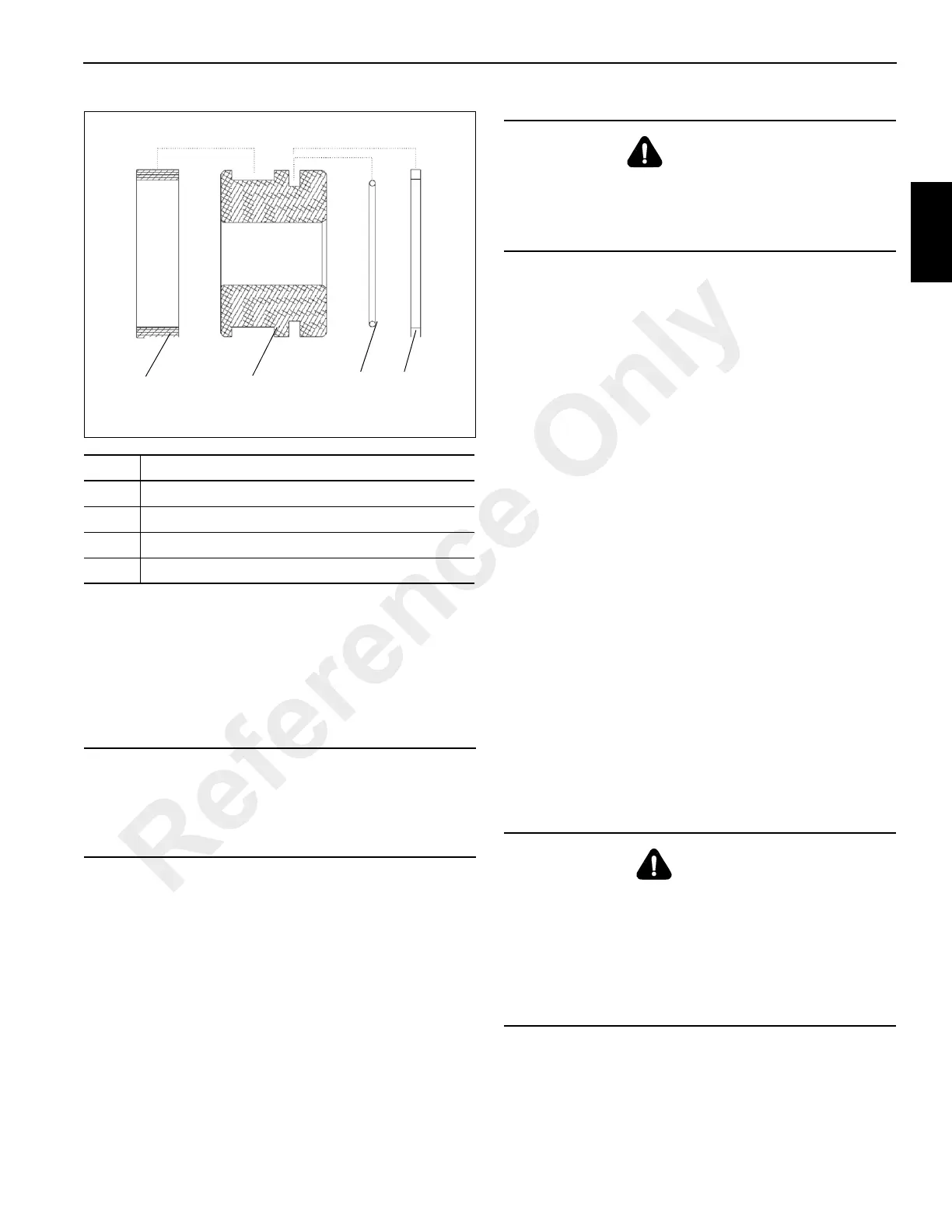
Item Description
1 Wear Ring
2Piston
3 O-ring (Energizer)
4 Piston Seal
CAUTION
Ensure there are no rags or other contaminants left in the
cylinder barrel before installing rod assembly. Lubricate
the barrel ID with hydraulic oil to ease the rod assembly
installation.
WARNING
Before testing, ensure all fittings, hoses, ball valves, and
pump components are rated higher than test pressures.
Do not use air pressure to cycle or pressurize the cylinder.
Failure to do so could result in personal injury or death.
DANGER
Do not use air pressure to remove the rod. Use only a
source of controlled hydraulic oil pressure if the rod is
hard to move.
CAUTION
Exercise extreme care when handling or setting down the
rod. Damage to the rod surface may cause unnecessary
maintenance and expense.
Reference Only