HOIST AND COUNTERWEIGHT TMS700E SERVICE MANUAL
5-2 Published 01-29-2015, Control # 512-01
3. Tag and disconnect the electrical wires to the hoist
rotation indicator sensor box.
4. Tag and disconnect the electrical wires to the hoist motor
control valve.
5. Remove the hoist mounting nuts, bolts, washers, and
shims (if shims are used, mark their location).
NOTE: The GHP 30A model hoist assembly, less the
cable, weighs approximately 650 kg (1430 lb). If
there is only one hoist on the superstructure, there
will be an extra counterweight plate weighing about
672 kg (1480 lb) in place of the auxiliary hoist.
6. Using an adequate lifting device, remove the hoist from
the crane.
Installation
1. Ensure the mounting plate and hoist pads are clean and
free from debris and the hoist has not been damaged
during handling.
2. With the hoist supported by a suitable lifting device,
position the hoist on the mount.
3. Check the hoist to boom alignment according to Hoist to
Boom Alignment, page 5-6.
4. Place a level between the boom pivot shaft bushings.
5. Place a level across the top of the hoist drum and
determine if the hoist is sitting in the same plane in
relation to the level positioned between the boom pivot
shaft bushings.
6. With the hoist level, check to determine if all the hoist
mounting pads are in contact with the mounting plate by
rocking the hoist.
7. Keeping the hoist level, use a feeler gauge to determine
the amount of gap existing between the pads and the
mounting plate.
8. Add shims to satisfy any existing gaps. Altering the shim
thickness to fit a tapering gap is acceptable. Install the
bolts, washers, and nuts. Tighten bolts; refer to
Fasteners and Torque Values, page 1-12 for the torque
value for the hoist mounting bolts.
9. Remove the lifting device from the hoist.
10. Connect the hydraulic lines to the hoist. Ensure the
proper lines are connected to the correct ports as
marked during removal.
11. Connect the electrical wires to the hoist motor control
valve as marked during removal.
12. Connect the electrical wires to the hoist drum rotation
indicator sensor box as tagged during removal.
13. Install the cable, following the procedures outlined under
Installing Cable on the Hoist, in the Operator’s Manual.
Functional Check
1. Attach a test weight to the hook and raise and lower the
load several times.
2. Check the hoist for smooth operation of the hoist motor
and brake system.
3. Ensure the hydraulic connections are secure and free
from leaks.
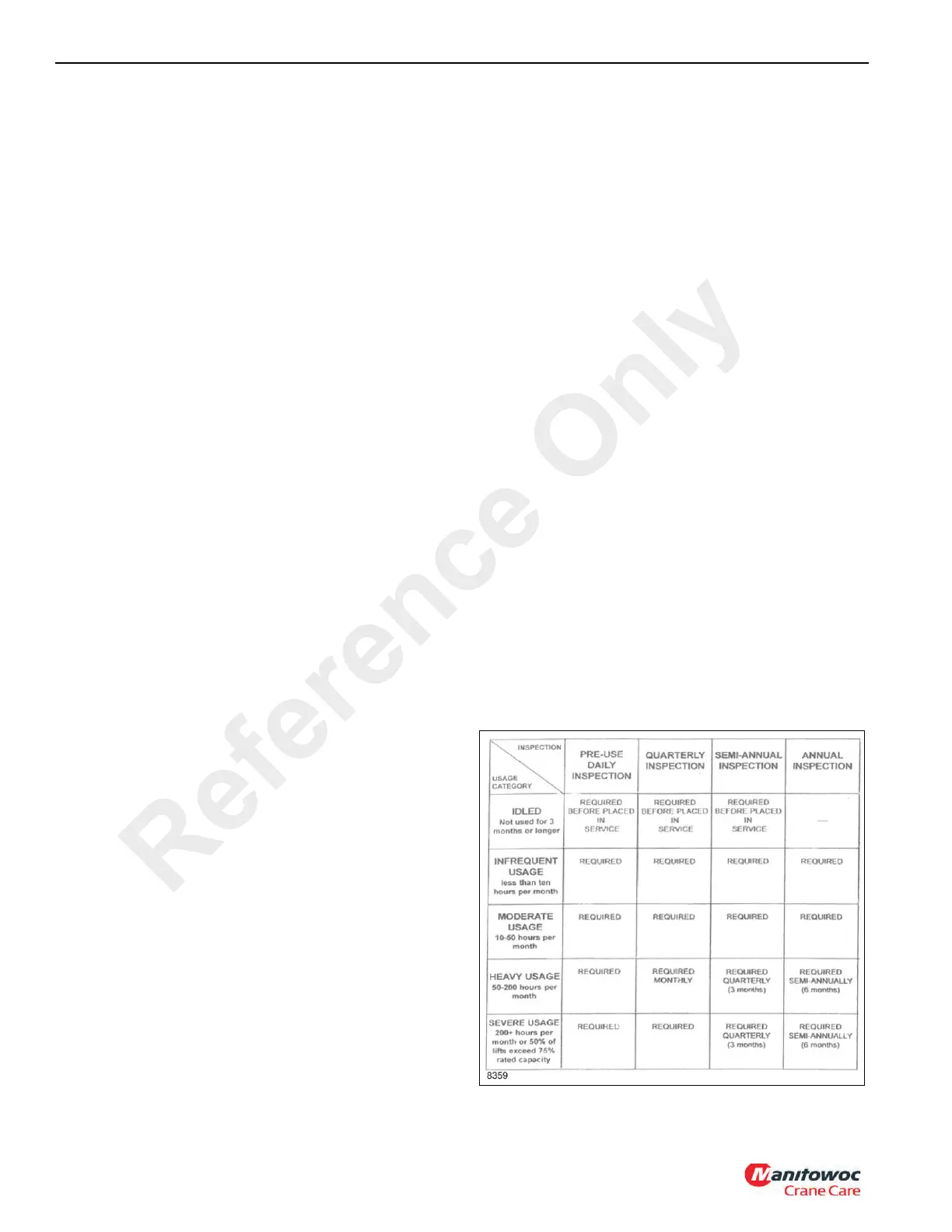
Usage and Inspection
Inspection procedures for hoists are divided into five general
categories based upon their usage or duty cycle, which in
turn determines appropriate intervals for inspections. The
usage categories must be assigned by the crane user on a
consistent crane-by-crane basis. The five crane/hoist usage
categories are as follows:
Idled - The crane/hoist has not been used for three months.
Infrequent Usage - The crane/hoist is used less than ten
hours per month based on a three month average
Moderate Usage - Crane/hoist used 10 - 50 hours per month
based on a three month average.
Heavy Usage - Crane/hoist used 50 - 200 hours per month.
Severe Usage - Crane/hoist is operated more than 200
hours per month OR where 50% of the lifts exceed 75% of
the rated capacity for the hoist.
The following chart lists the inspections that are required for
each type of usage category.
Reference Only

 Loading...


