Grove Published 01-29-2015, Control # 512-01 2-45
TMS700E SERVICE MANUAL HYDRAULIC SYSTEM
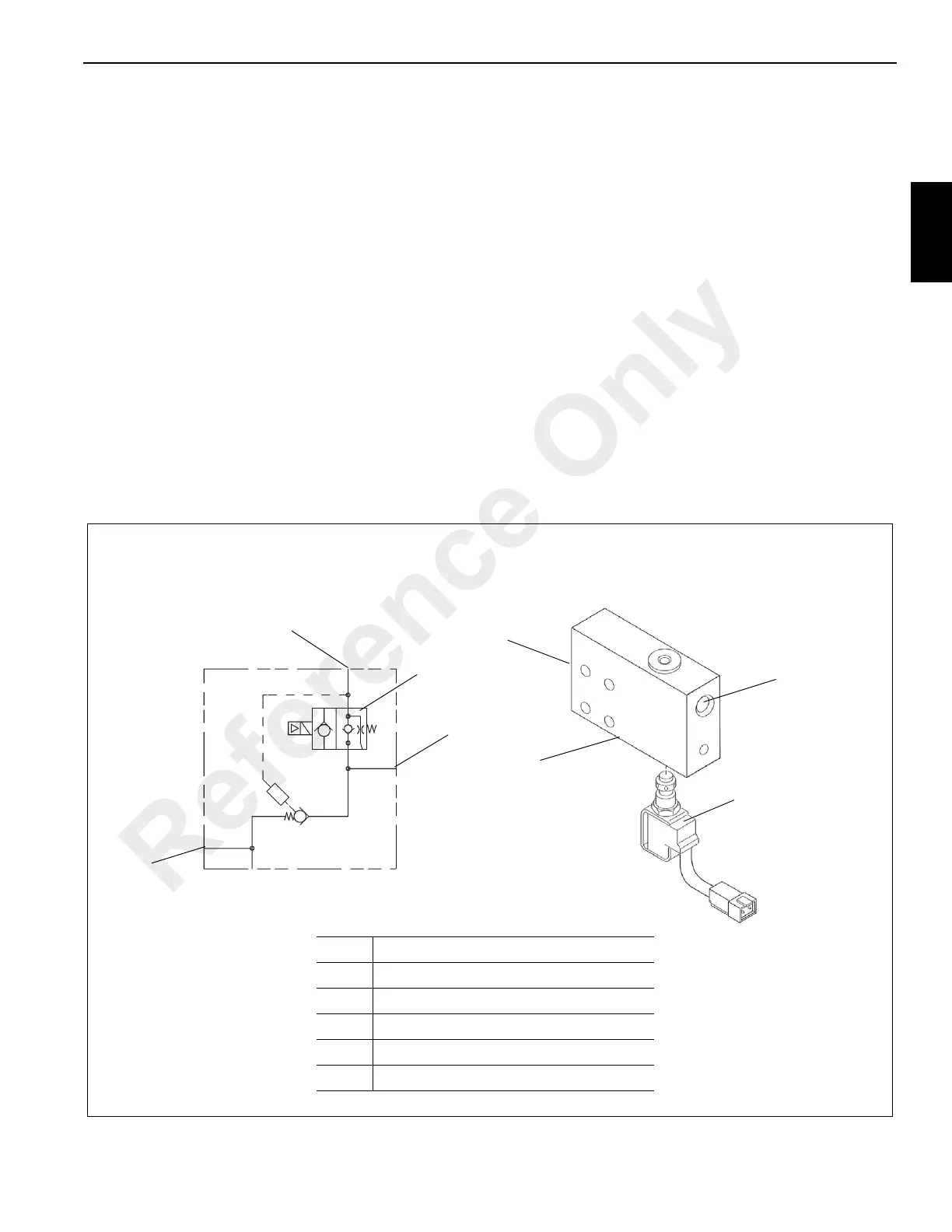
HIGH SPEED BOOST SELECTOR VALVE
Description
The high speed boost selector valve (Figure 2-32) is located
on port #4 of the hydraulic swivel spool. Output from pump
number 1, section 2 passes through the high speed boost
selector valve. When the valve is de-energized, the oil flows
to the normal delivery. When the valve is energized, the oil is
combined with the output of pump number 1, section 1 to
provide additional oil capacity to the section 1 functions. With
the valve in the energized position, the outriggers are
inoperative.
The high speed boost selector valve consists of a valve body,
one normally open two-way, two position solenoid valve, and
a pilot to close poppet check valve.
Maintenance
Removal
1. Tag and disconnect the electrical connectors to the
valve.
2. Tag and disconnect the hydraulic hoses from the valve.
Cap or plug the lines and ports.
3. Remove the hydraulic fitting securing the valve to the #4
port of the hydraulic swivel spool. Remove the valve.
Installation
1. Install the valve to the #4 port of the hydraulic swivel
spool and tighten the fitting.
2. Connect the hydraulic hoses to the ports on the valve as
tagged during removal.
3. Connect the electrical connectors to the valve as tagged
during removal.
4. Start the engine and check valve and hoses for leaks.
Make repairs as needed.
1
3
4
2, 5
1
4
3
2
Item Description
1Port B
2 Port P1 - From Pump No. 1 (Not Shown)
3 Solenoid Valve
4 Port P2 (Not Shown)
5 Outlet Port - To Swivel Port 4
FIGURE 2-32
Reference Only

 Loading...


