UNDERCARRIAGE TMS700E SERVICE MANUAL
8-54 Published 01-29-2015, Control # 512-01
valves. One valve controls the front #2 axle service brakes,
one valve controls the rear axle service brakes, and the other
valve controls the rear parking brakes. Air pressure, which
controls the valve, enters through the service port to either
deliver or exhaust air pressure from the circuits serviced by
the relay valve.
Dual Brake Valve
The dual brake valve is a suspended, pedal operated brake
valve which has two separate supply and delivery circuits.
The valve is located under the front console to the right of the
steering column. The valve provides the driver with a
graduated control for applying the service brakes or the
parking brakes through the spring brake control valve.
Spring Brake Control Valve
The spring brake control valve is located on the right side of
the carrier frame. The purpose of the valve is to supply a
specific, limited hold off pressure to the spring brakes, and in
the event of loss of primary pressure, to modulate the spring
brakes through use of the dual brake valve.
Park Brake Control Valve
The park brake control valve is an on/off push/pull control
valve located on the front console. When the air pressure
reaches 3.40 bar (50 psi) and the button is pushed in, the
park brakes are disengaged. The button will pop out when
the air pressure falls below 2.80 bar (40 psi) exhausting the
delivery line and engaging the brakes.
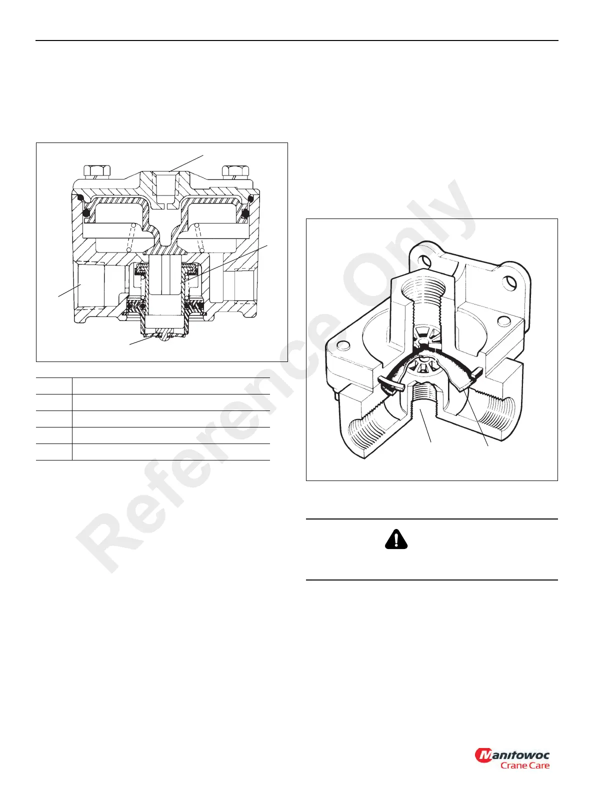
Quick Release Valve
There are two quick release valves (see Figure 8-64) used in
the air system. One is used for front axle #1 service brakes,
and the other is used for right side only rear spring brakes.
The quick release valve is an air valve used to exhaust air
pressure from the brake chambers to speed up the brake
release by reducing the distance the air would have to travel
back to the operating valve exhaust port.
Maintenance
Air Compressor
NOTE: Detailed maintenance instructions for the air
compressor are contained in the Engine Service
Manual.
Removal
1. Chock the wheels and depressurize both primary and
secondary air circuits.
2. Open the engine compartment to gain access to the air
compressor.
Item Description
1 Supply Port
2 Exhaust Cover
3 Service Port
4 Inlet/Exhaust Valve
WARNING
Depressurize both air systems completely before
disconnecting air lines or components.
Exhaust Port
Diaphragm
FIGURE 8-64
Reference Only

 Loading...


