Grove Published 01-29-2015, Control # 512-01 2-47
TMS700E SERVICE MANUAL HYDRAULIC SYSTEM
NEEDLE VALVE
Description
The two lift cylinder mounted needle valves are used to
connect the rod and piston sides of the boom lift cylinder
together to allow the boom to float when the boom is in the
trailing boom mode.
The knob adjustable needle valve is installed into a manifold.
Turning the knob counterclockwise opens the valve to allow
the boom flotation and clockwise rotation closes the valve to
return to normal boom lift cylinder operation.
Maintenance
Removal
1. Tag and disconnect the hydraulic lines from the valve
and cap or plug all openings and remove valve.
Installation
1. Connect the hydraulic lines as tagged during removal.
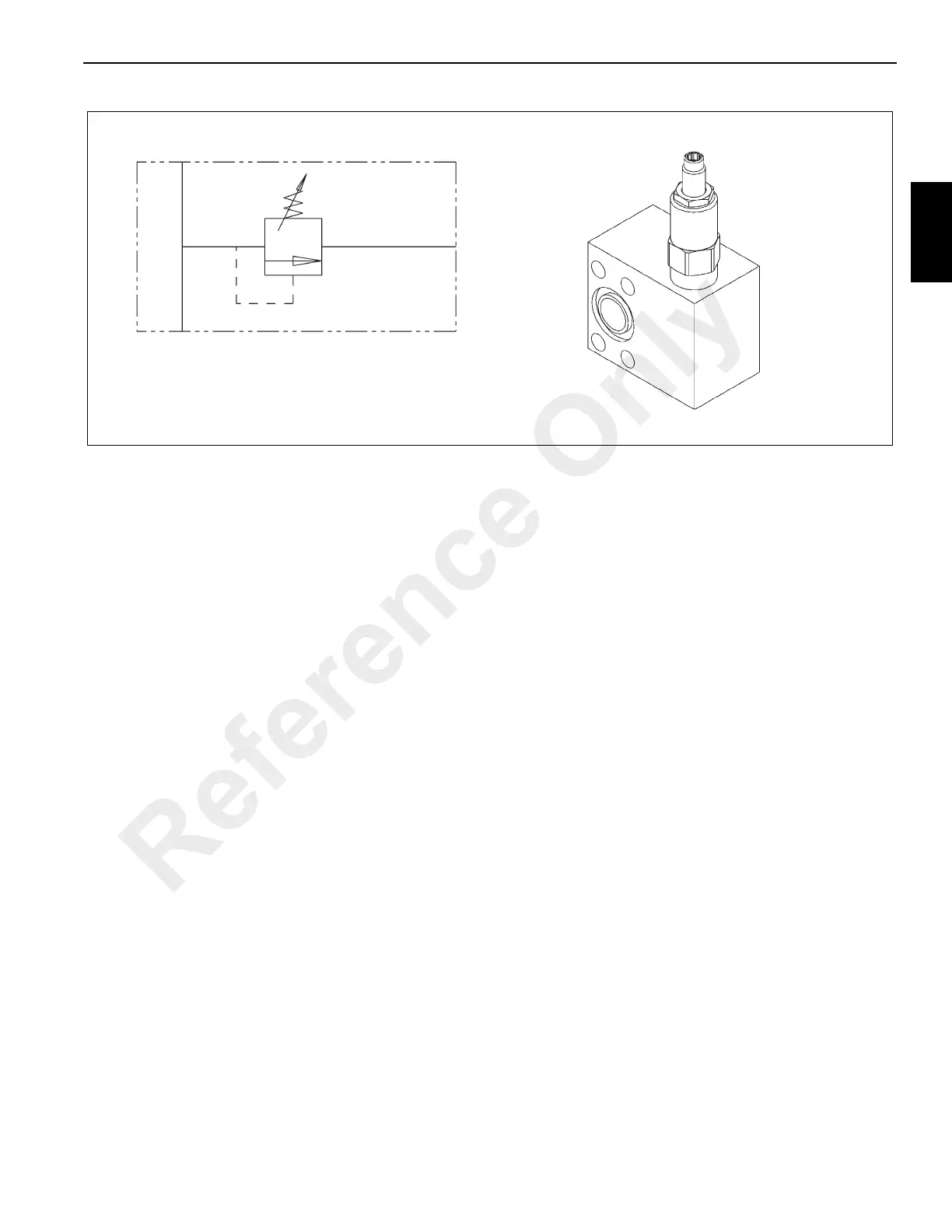
NEEDLE VALVE WITH REVERSE FREE
FLOW CHECK
Description
A needle valve with a reverse free flow check is used to
prevent pressurization of the lift cylinder when the boom lift
cylinder is in the trailing boom mode.
The knob adjustable needle valve and check valve is
installed into a manifold. Turning the knob counterclockwise
opens the valve to allow the normal boom lift operation and
clockwise rotation closes the valve for trailing boom mode.
Maintenance
Removal
1. Tag and disconnect the hydraulic lines from the valve
and cap or plug all openings and remove valve.
Installation
1. Connect the hydraulic lines as tagged during removal.
SWING POWER BRAKE VALVE
Description
The swing power brake valve (Figure 2-35) is used to
provide hydraulic pressure to the piston of the swing brake to
apply the brake. The valve receives its supply of oil from the
main directional control valve pilot generator port.
Depressing the brake pedal causes hydraulic oil to flow to
the top of the brake piston where, combined with spring
tension, the total force overcomes the brake release
pressure and applies the brake. When the valve is released,
excess hydraulic oil flows from the valve to the case drain
manifold and back to the reservoir.
Maintenance
Removal
1. Tag and disconnect hydraulic lines attached to the brake
valve. Cap or plug the lines and ports.
2. Remove the four bolts, lockwashers, flat washers, and
nuts which secure the brake valve to the cab floor.
Remove the brake valve.
6874-2
6874-1
FIGURE 2-34
T1
S
P
Reference Only

 Loading...


