Grove Published 01-29-2015, Control # 512-01 2-19
TMS700E SERVICE MANUAL HYDRAULIC SYSTEM
VALVES
General
This subsection provides descriptive information for all the
hydraulic valves used on this crane. For a listing of all valves,
the circuit they are used in, and their physical location, refer
to the Valve Usage Table, below. Also, refer to the following
table for valve locations. The description of each valve given
here is for the valve itself. For information on how each valve
functions in the individual circuits, refer to the description and
operation procedures of that circuit.
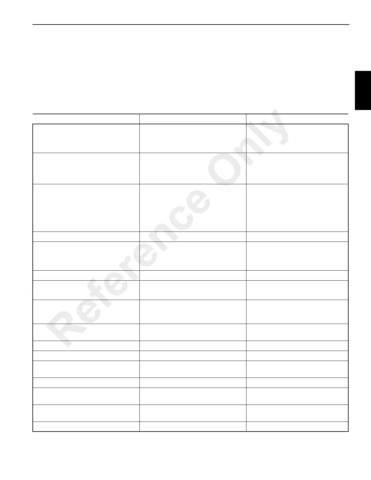
Table 2-1
Valve Usage Table
Valve Name Circuit Used In Physical Location
Directional Control Valves Boom Lift/Telescope/Hoist(s)
Swing
Counterweight Removal
Superstructure right side
Superstructure right side
Superstructure under hoists
Manifold
• Swing brake release
• Crane function
Swing
HRC lockout (crane functions)
Superstructure right side
Hydraulic Remote Control Valve Boom lift
Telescope
Main hoist
Auxiliary hoist
Swing
Cab seat arm rests (2)
Swing Power Brake Valve Swing Superstructure cab floor
Holding Valves Boom lift
Telescope (2)
Counterweight removal (2)
Lift cylinder (bolt on manifold)
Telescope cylinder (cartridge style)
Removal cylinder (cartridge style)
Hoist Motor Control Valve (1 of 2) Hoist(s) Both hoists (see Hoist Section)
Check Valves (2) Return circuit
Return circuit
One on swing outlet
One in parallel with oil cooler
Outrigger Selector Valve Outrigger On front face of carrier frame front
cross member forward of hydraulic
swivel
Outrigger Control Manifold (2) Outriggers 4 stack on rear outrigger box; 5 stack
on front outrigger box
Pilot Operated Check Valve Outrigger Port block of each jack cylinder (4)
Swing Speed Flow Control Valve Swing In-line between swing work port lines
Priority Flow Divider Valve Optional air conditioner Rear frame tunnel forward of
hydraulic swivel
High Speed Boost Selector Valve Hoist, boom lift and telescope On swivel port #4
Front Center Jack Relief Valve Outrigger Front outrigger box under left rear
frame rail
Pump Mounted Relief Valve Outrigger/Main Crane Circuit Mounted on the outlet of hydraulic
pump #2 section #2
Needle Valve (2) Trailing boom option Boom lift cylinder
Reference Only

 Loading...


