Grove Published 01-29-2015, Control # 512-01 8-35
TMS700E SERVICE MANUAL UNDERCARRIAGE
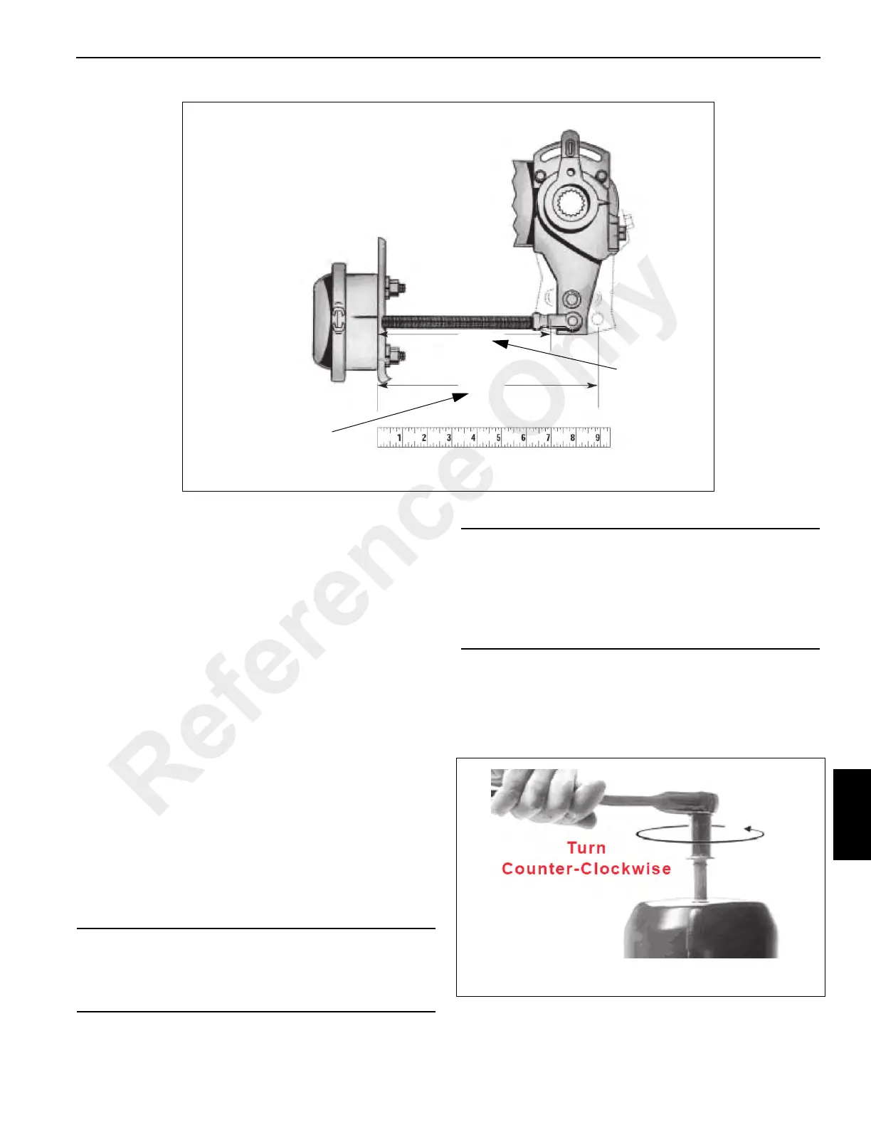
6. Starting with 6.21 to 6.89 bar (90 to 100 psi) air tank
pressure in both primary and secondary systems, fully
apply service brakes and hold brakes on. Do not pump
the brakes. Measure between the same points as in step
5 on each brake. This is Dimension “B” (Figure 8-35).
7. Subtract Dimension “A” from Dimension “B” for each
brake position (Figure 8-35). This value cannot exceed
5 cm (2 in) on the front brakes or 6.3 cm (2.5 in) on the
rear brakes.
8. If any brake exceeds values shown in step 7, the brake
must be re-adjusted per the Brake Free Play
Measurement and Adjustment procedure that follows in
this section.
9. If after adjustment the requirements in step 7 cannot be
met, contact your distributor or Manitowoc Crane Care.
The crane can not be driven on public roads until
repaired.
Brake Free Play Measurement and
Adjustment
The following procedure is required to ensure that the free
play of the brakes is within required values.
1. Chock the wheels and release the parking brakes.
2. Turn the integral release bolt counterclockwise using a
3/4 inch socket wrench (Figure 8-36), until the power
spring is fully caged or compressed. Full cage position
requires approximately 22 to 23 turns for 76 mm
(3.00 in) stroke units.
7094-1
FIGURE 8- 35
A
B
(Fully Retracted)
(Brake Application at 6.21 to 6.89
bar (90 - 100 psi) reservoir
pressure)
CAUTION
If the brake is equipped with a spring type parking
chamber the spring must be caged before taking
measurements.
CAUTION
Do not use an impact wrench on bolt.
For easier turning of the release bolt, apply 6.55 to
8.62 bar (95 to 125 psi) air pressure to the air inlet port
marked “Spring”. After caging, completely exhaust air
from the spring chamber.
Reference Only

 Loading...


