Grove Published 01-29-2015, Control # 512-01 5-9
TMS700E SERVICE MANUAL HOIST AND COUNTERWEIGHT
hardware. Do likewise for the cable guide roller and
shaft and attaching hardware.
2. Inspect each shaft and roller for cracks, scoring, or
grooving. Replace if necessary.
3. Inspect the springs for proper length, tensile strength,
and lack of damage. Replace both springs as a pair if
either is defective.
Assembly
1. Secure the cable guide roller to the two support end
brackets of the hoist with its shaft and attaching
hardware.
2. Secure the cable tension brackets to the two support
end brackets of the hoist with attaching hardware.
3. Secure the cable guard roller to the cable tension
brackets with its shaft and attaching hardware.
4. Attach each of the two springs to its related eyebolt and
jam nut that attach to the spring adjusting bracket on
each of the two support end brackets of the hoist. Attach
the other end of each spring to the spring hole of its
related cable tension bracket.
5. Adjust each spring’s jam nut and eyebolt until there is a
distance of 42 mm (1.7 in) between the jam nut and the
threaded end of the eyebolt.
6. Ensure the cable guide roller can turn, and that it
touches the cable along its cable-touching length.
7. If the cable guard roller’s bearings have grease fittings,
apply EP-MPG grease to them. If the cable guide roller’s
bearings have grease fittings, apply EP-MPG grease to
them.
3
5
3
6
2
4
7
1
3
4
6928-2
6928-1
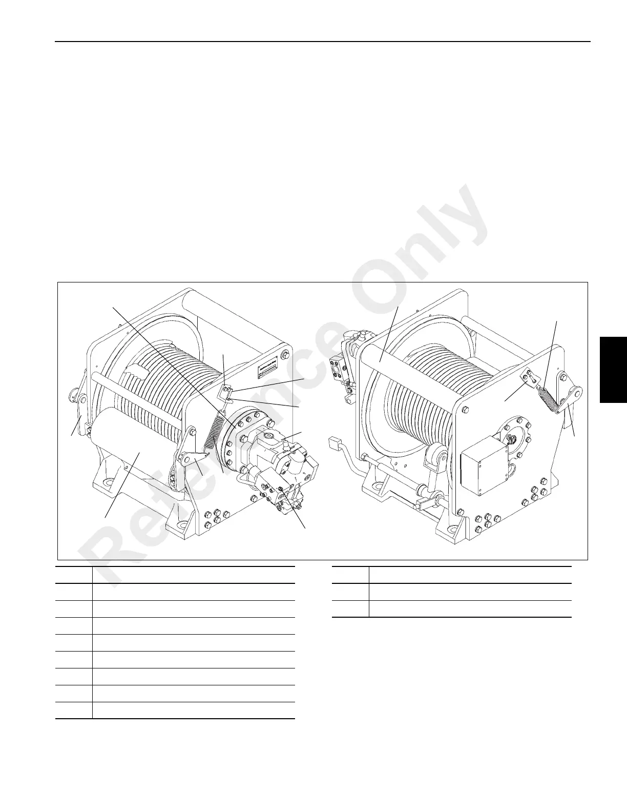
FIGURE 5-4
5
8
9
10
Item Description
1 Cable Guard Roller
2 Cable Guide Roller
3 Cable Tension Bracket
4 Spring Adjusting Bracket
5Spring
6 Eyebolt
7Jam Nut
8Motor
9 Brake Valve
10 Brake Clutch and Brake Cylinder
Item Description
Reference Only