Grove Published 01-29-2015, Control # 512-01 8-29
TMS700E SERVICE MANUAL UNDERCARRIAGE
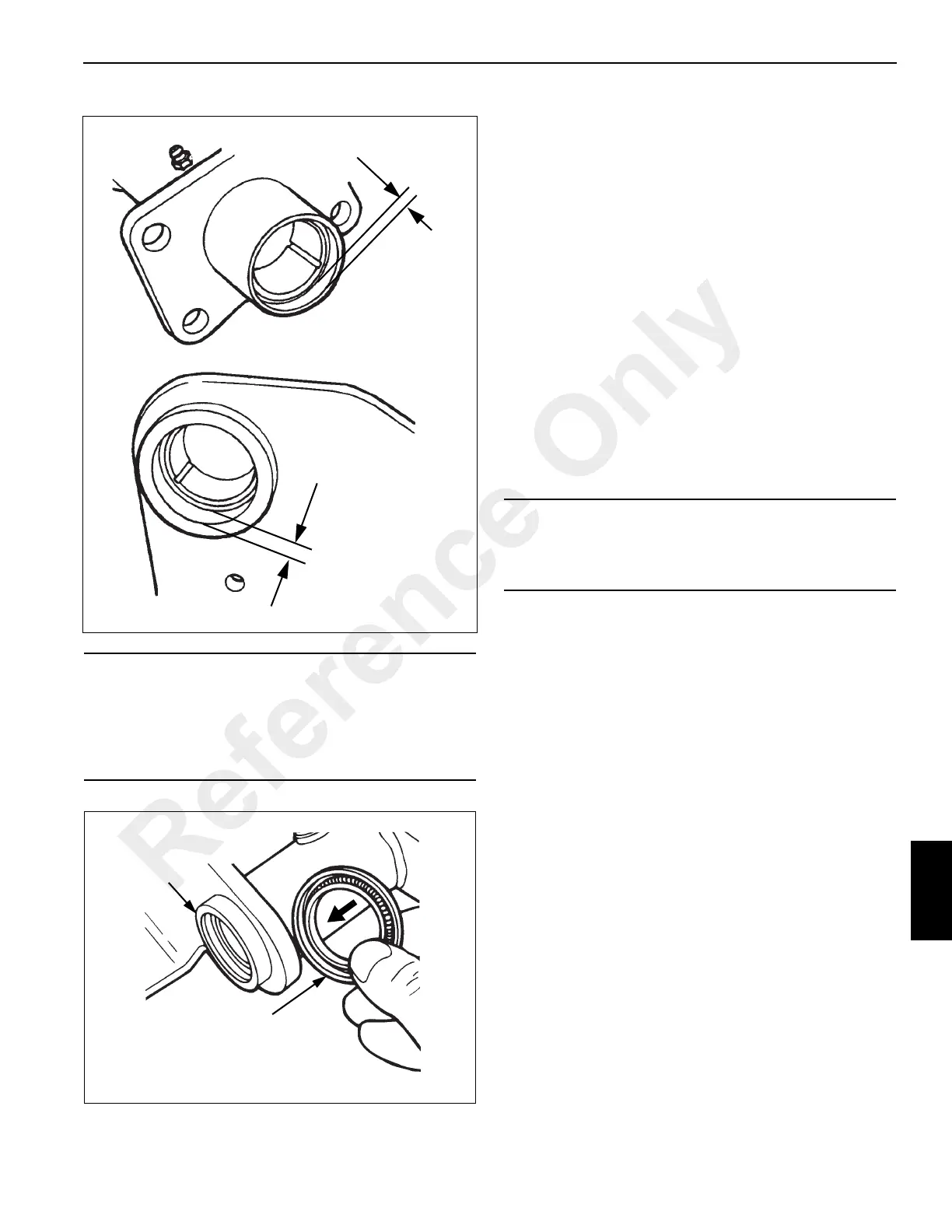
5. Install new grease seals with a piloted driver so the seals
are flush with the end of the air chamber bracket tube
(see Figure 8-21).
Assembly
1. Position the spider on the axle flange and install
attaching bolts and nuts. Place hardened washers under
the bolt head.
2. Position the dust shield against the spider. Install all
attaching screws finger tight. Torque screws 16.9 to
20.3 Nm (150 to 180 lb-in).
3. Align the air chamber bracket with the holes on the
spider and secure with the bolts and lock washers.
Torque 88 to 115 Nm (65 to 85 lb-ft).
4. Installation of camshaft is as follows:
a. Check for correct camshaft by rotating the camshaft
in the direction of the air chamber push rod
extension. The roller should start to ride up on the
convex side of the cam head.
b. Apply a thin film of chassis grease on the inside of
the camshaft bushing, seals, and spline area.
c. Place the cam head washer on the camshaft under
the cam head with the cast spider arrow pointing
toward the center of the spider.
d. Carefully slip the camshaft into the mounting
position.
5. Install the slack adjuster. Refer to Automatic Slack
Adjuster, page 8-44.
6. Installation of brake shoes is as follows:
a. Lubricate the shoe roller recess with chassis
grease. Do not get grease on the cam head surface.
b. Hook the ends of the new retainer springs into the
holes on both shoe webs with the hooks pointing
out.
c. Position the upper and lower shoes around the
anchor pin. Install a new shoe return spring.
d. Assemble the roller retainer on both ends of the
roller.
e. Stretch the return spring and insert the roller and
retainer on the lower shoe web.
f. Position the roller assembly in the recess. Squeeze
the loops of the retainer and rotate to snap loops
CAUTION
Seals must be installed with the lip side (spring side) of
both seals facing toward the slack adjuster end of the
bracket. Improperly oriented seals may allow grease to
exit the camshaft head end of air chamber bracket and
contaminate lining material.
At slack adjuster end,
recess bushing 17.5
mm (0.687 in)
At cam head end, recess
bushing 7.1 mm (0.281 in)
FIGURE 8-22
Install seals flush
with end of tube.
Lip side of both seals
must face toward slack
adjuster end of bracket
FIGURE 8-23
CAUTION
Do not get grease on cam head surface. The cam surface
must be free of oil, grease, and other contaminants for
efficient operation.
Reference Only

 Loading...


