HYDRAULIC SYSTEM TMS700E SERVICE MANUAL
2-8 Published 01-29-2015, Control # 512-01
Hydraulic oil flowing from this valve bank returns to the
reservoir filter.
Section One also supplies the swing brake and armrest
lockout manifold and the swing power brake valve. The
manifold contains the swing brake release valve and the
controller armrest lockout valve. Hydraulic oil flowing through
the manifold supplies the hoist, swing, telescope, and lift
hydraulic remote control valves. Section One also supplies
the counterweight removal control valve.
Section Two of the No. 1 hydraulic pump supplies the
integrated outrigger valve, and all outrigger functions and the
center front jack functions as well.
Output from Section Two passes through the high speed
boost selector valve. When the valve is de-energized, the oil
flows to the integrated outrigger valve. When the valve is
energized, it closes to cut off flow to the integrated outrigger
valve. Oil flow from Section Two combines with the output of
Section One to provide additional hydraulic force to the
Section One functions.
Section Three of the No. 1 hydraulic pump supplies the
optional superstructure cab air conditioning compressor
motor. If the crane does not have this feature, the section’s
output returns to the reservoir.
No. 2 Pump
The engine drives the No. 2 pump at 1.16 times engine rpm.
Priority flow of 37.9 lpm (10 gpm) goes to the front steering
gear and the remainder goes to the auxiliary cooler circuit.
No. 3 Pump
The engine drives the No. 3 pump off the back of the air
compressor at 1.16 times engine rpm.
Output supplies the swing directional control valve and swing
drive motor.
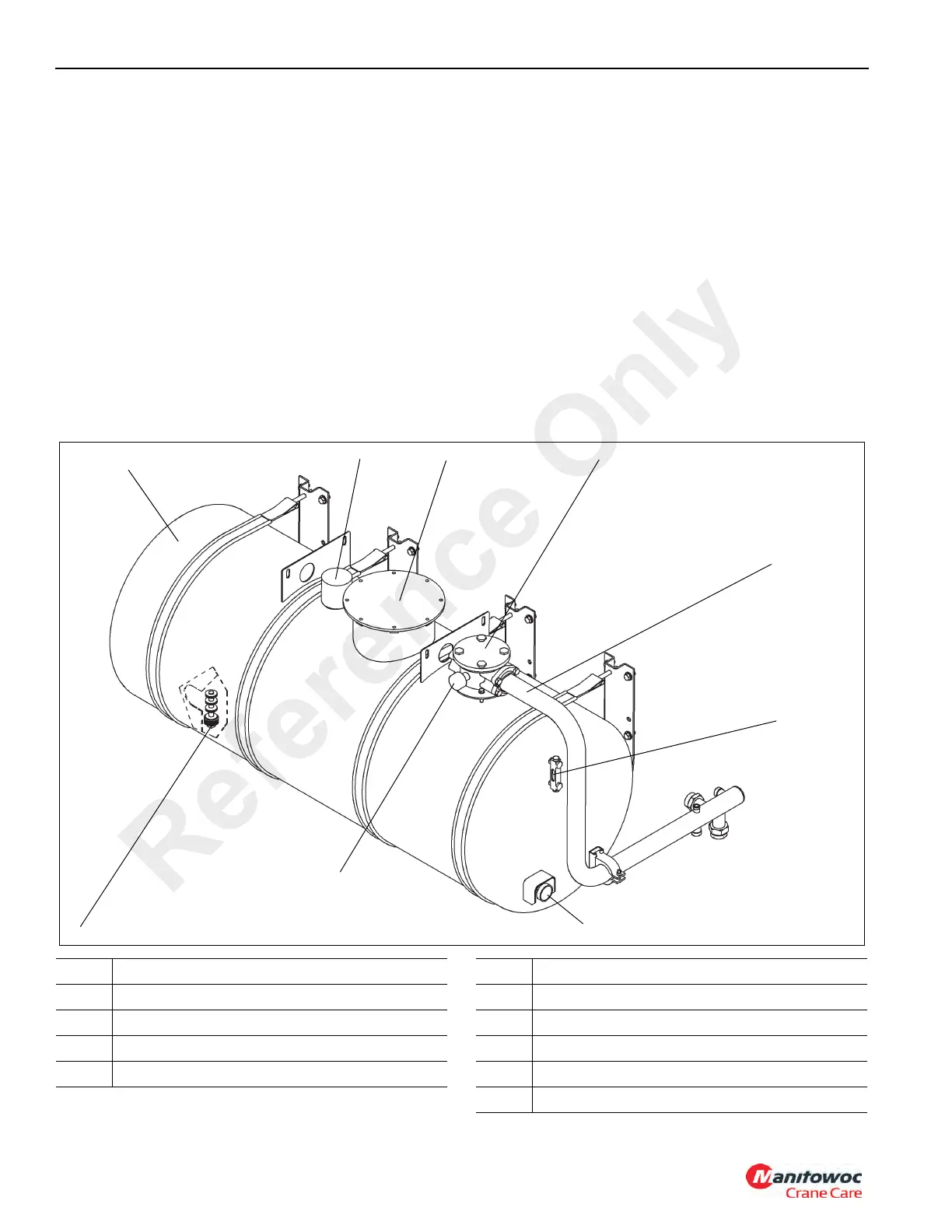
Item Description
1 Reservoir Assembly (Hydraulic Tank)
2Drain Plug
3 Breather and Fill Neck
4 Access Cover
Item Description
5 Return Filter Assembly
6 Return Manifold Tube Assembly
7 Oil Level Gauge
8 Temperature Gauge
9 Bypass Gauge
Reference Only

 Loading...


