Technical Information
38
G 1xxx/G 2xxx
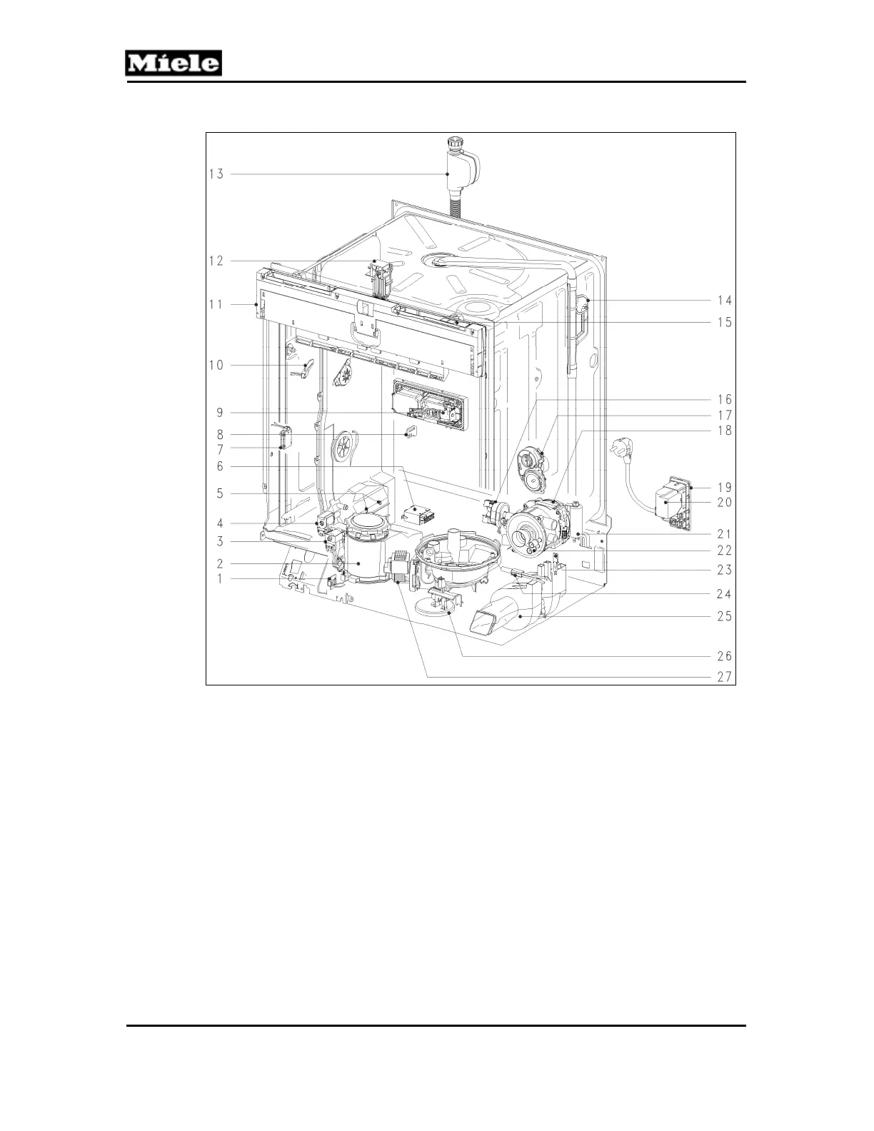
3.7 G 2670 (Excella with Incognito)
Figure D-26: G 2670 Component Layout (US only)
1
Salt float switch, B8/2
15
Main switch, S2
2
Salt container
16
Heater pressure switch, B1/13
3
Reactivation solenoid, Y38
17
Slide shutter, M24 and B3/12
4
Wash-water hardness solenoid, Y5
18
Circulation pump (MPEW), M6
5
Sensor softener, 10N1
19
Terminal block, X3/1
6
Heater relay, K1/1
20
Interference suppression, Z1
7 Middle and bottom spray arm sensors, 4N1
and 5N1
21
Circulation pump capacitor, C6
8
Rinse aid float switch, B8/1
22
Heater, R1
9
Combination dispenser solenoid, Y50
23
Speed sensor, B3/9
10
Flow meter, B3/4
24
Temperature sensor (NTC), R30
11
Electronic modules, 1N1 and 2N1
25
Fan, M2
12
Door contact switch, S24
26
Overflow float switch, B8/3
13
Water intake solenoid, Y2
27
Drain pump, M8
14
Turbidity sensor, B3/10
 Loading...