2-7
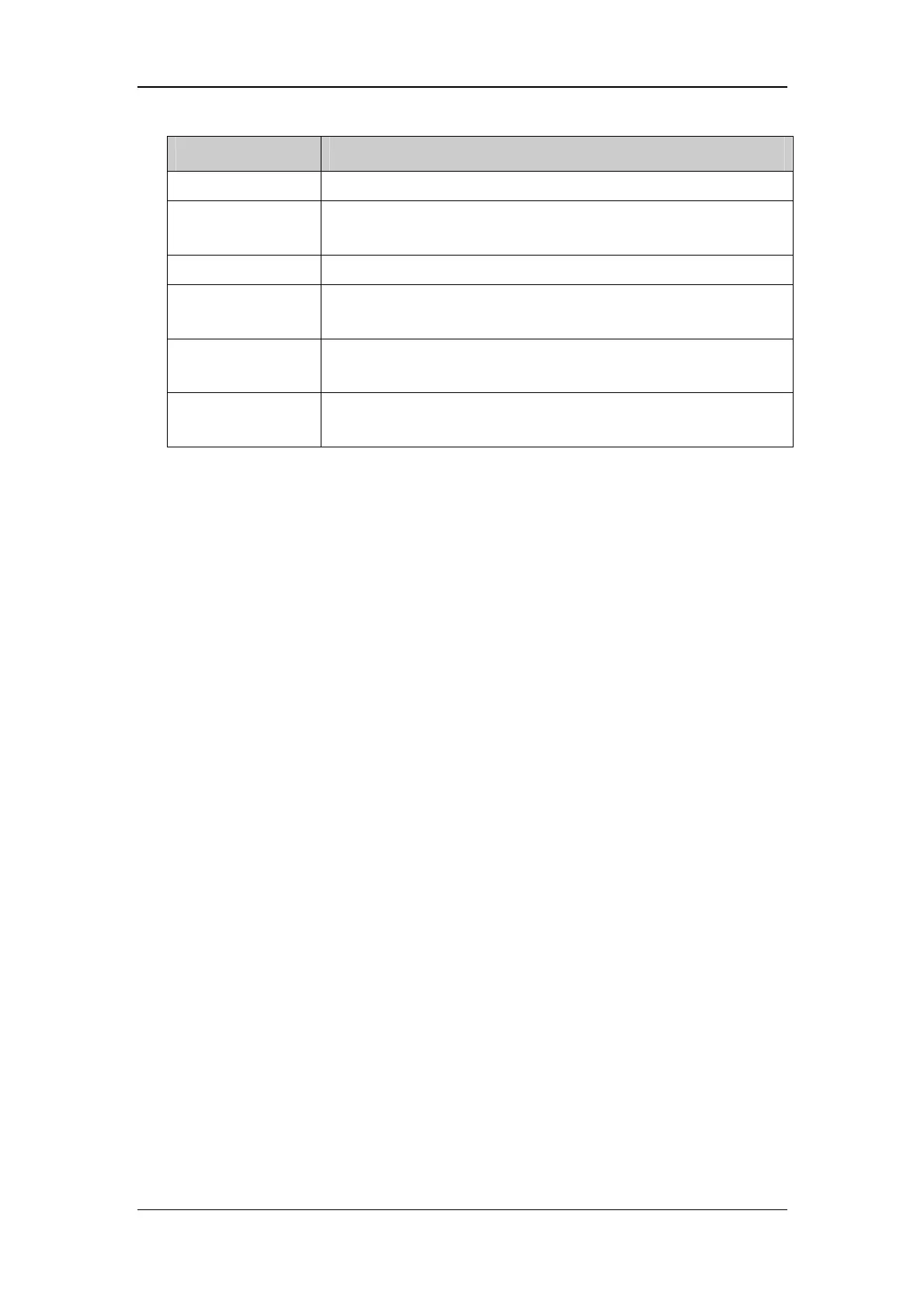
Module Description
Power interface Introduces a DC from the main board.
Power module
Converts the input power into voltages that fit each module and then
forwards them to each module.
CPU Control the communications between modules.
Signal interface
Control the communications between the main board and the
recorder CPU.
Motor drive circuit
Receives the control signals from the CPU and then forwards them to
the step engines.
Button & LED
board
Includes one button and one LED which are directly controlled by
the CPU.
Speaker
The speaker provides sound for alarms, key strokes, heart beats and pulse, and allows PITCH
TONE and multi-level tone modulation. It is connected with the main board and is directly
driven by the main board.
2.3.3 Processing and Communications System
Main Board
The main board is the heart of the patient monitor. It implements a series of tasks including
input & output control, data storage and processing, display processing, system control,
communication management, printing management and alarming, etc.
The main board comprises the CPU board and mother board. The following diagram shows
interfaces to other components.
 Loading...