Home
Mindray
Medical Equipment
DC-70 Exp
Mindray DC-70 Exp User Manual
5
of 1
of 1 rating
295 pages
Give review
Manual
Specs
To Next Page
To Next Page
To Previous Page
To Previous Page
Loading...
8-
28
Fiel
d Replaceable
Unit
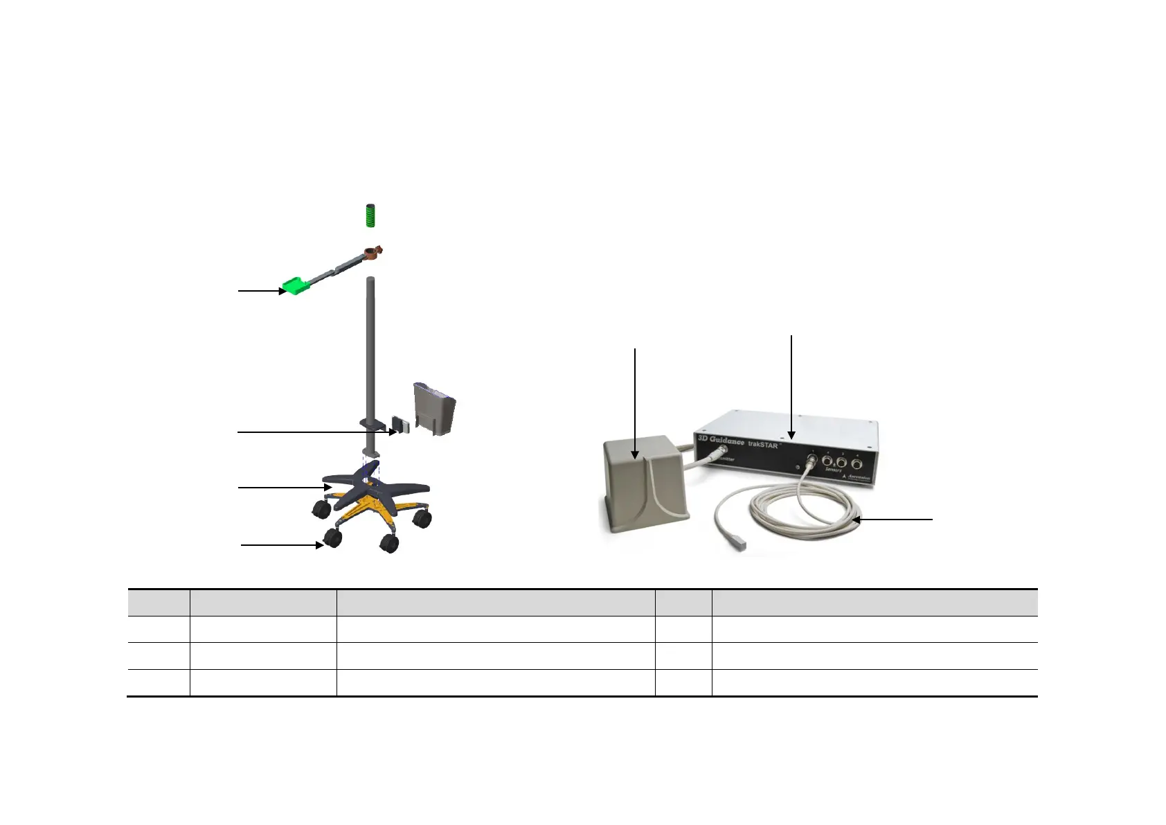
8.2.9
Fusion Imaging
Assembly (I
0)
No.
Order Number
Part Name
Q
t
y.
Remark
I1
11
5
-
034852
-0
0
cantilever assembly
1
I2
11
5
-
040847
-
00
Connect
Base Assembly
1
I3
043
-
006786
-
00
Base Cover(T
ransport)
1
I5
I6
H7
I4
I3
I2
I1
135
137
Table of Contents
Table of Contents
3
Revision History
9
Intellectual Property Statement
10
Applicable for
10
Statement
10
Customer Service Department
11
Safety Precautions
13
Meaning of Signal Words
13
Symbols
13
Meaning of Safety Symbols
13
Warning Labels
14
General Symbols
14
Safety Precautions
16
Electric Safety
16
Mechanical Safety
17
Personnel Safety
17
Other
17
Specifications
19
Overview
19
Intended Use
19
Introduction of each Unit
19
Peripherals Supported
28
Specifications
28
Dimensions & Weight
28
Electrical Specifications
28
Environmental Conditions
28
Monitor Specification
29
System Installation
31
Preparations for Installation
31
Electrical Requirements
31
Installation Conditions
32
Confirmation before Installation
33
Unpacking
33
Unpacking Process
33
Check
35
Installation of Main Unit
35
Open up the Monitor
36
Connecting the Power Cord
36
Connecting ECG
37
Installing Probe/Gel Holder
37
Connecting the Transducer
38
Installing Peripherals
39
Connecting the Footswitch
39
Installing a Graph / Laser Printer
40
Installing Video Printer
42
Position a Printer
42
Installing Barcode Scanner
43
System Configuration
44
Running the System
44
Enter Doppler
44
System Preset
46
Print Preset
47
Network Settings
47
Network Configuration
49
Security
50
DICOM/HL7 Preset
51
Check System Information
53
Product Principle
55
Hardware System Diagram
55
Ultrasound Front-End Unit
56
Probe Board
57
TR Board
58
CW Module
59
Engine Board
59
Module
61
ECG Module
62
Ultrasound Back-End Unit
62
PC Module
63
PC Carrier Board
63
GPU Module
64
Storage Device
64
Wireless Network Module
64
IO Interface Module
64
Extension and Distribution
65
Video Extension Function
65
Audio Interface
66
SATA Interface
66
USB Distribution
66
Network Interface
67
PCIE Interface Distribution
68
Other IO Extension
68
Power Supply Unit
69
AC Connecting Board
70
AC-DC Module
70
To 12V Power Conversion Board
70
DC-DC Board
71
PHV Board
71
Time Sequence of Power-On
71
User Interaction Unit
72
Control Panel Assembly
72
Primary Display Assembly
73
Secondary Display Assembly
73
Function and Performance Checking Method
75
Note
75
System Running Status
75
Running Status
75
Working Condition
75
General Exam
76
Check Flow
76
Checking Content
76
Function Checking
79
Checking Flow
79
Performance Test
85
Test Process
85
Test Content
85
Software Installation &Maintenance
93
Enter Maintenance
93
Set Installment
93
Software Installation/Restoration
96
Enter Windows
96
Software Maintenance
96
Export Log
96
Fast Startup
97
Data Backup and Storage
100
Preset Data Management
100
Patient Data Backup and Restoration
101
Introduction on Hard Disk's Partitions
102
Adjustments
103
Monitor Adjustment
103
Position Adjustment
103
Brightness and Contrast Adjustment
104
Monitor Test
105
Touch Screen Test
106
Control Panel Adjustment
107
Caster Adjustment
108
Field Replaceable Unit
109
Exploded View
110
Assembly Exploded View
111
Monitor Assembly (A0)
111
Monitor Support Arm Assembly (B0)
113
Main Control Panel Assembly (C0)
115
Control Panel Support Arm Assembly (D0)
121
Main Unit Assembly (E0)
123
Base Assembly (F0)
132
Base Power Box Assembly (G0)
133
Cable (H0)
134
Fusion Imaging Assembly (I0)
136
Structure and Assembly/Disassembly
139
Structure of the Entire System
139
Preparation
140
Disassembly Tools Required
140
Engineers Required
140
Disassembly Requirements
140
Assembly/Disassembly
140
Display (Monitor) Assembly
142
Probe Board Assembly
143
Disassembling ECG Assembly
144
Outlet Fan
145
Disassembling Battery Assembly
146
IO Board/Wifi Board
147
Hdd
149
Electronic Assembly on the Base
151
DC Box Assembly
153
PC Assembly
155
Engine Board and TR Board
157
DVD
158
Inlet Fan
159
Motherboard
160
Control Panel Assembly
162
Face Cover Assembly of the Speaker/Speaker
167
Caster
169
Module Package
169
The Material Package of CW Assembly
171
Support Arm Assembly of the Control Panel
172
Support Arm Assembly of the Display
176
Keyboard Assembly
179
To 12V Power Conversion Board
180
AC-DC Module
180
AC Connecting Board
181
Power Input Assembly
182
Magnetic Generator Trolley
183
Magnetic Navigator
185
Optional Installation/Assembly
191
Installing Optional Software
191
System Diagnosis and Support
201
General Status Indicator
201
Indicators on Control Panel
201
Display Status Indicator
202
Status of Entire Device
203
Status Indicator of Gel Warmer
203
Get Entire Device Started
204
Power-On of Entire Device Supplied by AC
205
Start-Up Process of BIOS
205
Windows Start-Up
205
Start-Up of Doppler
206
Alarming and Errors
208
Battery Error
208
Abnormal Voltage of System Power
208
Fan Error
210
Gel Warmer Abnormality
212
Other Errors
213
Self Test
213
Self Test Introduction
213
Operation Procedure of Maintenance Self Test
213
User Self Test
218
Test Report
220
Care and Maintenance
223
Overview
223
Tools, Measurement Devices and Consumables
223
Routine Maintenance Items
223
Cleaning
225
System Cleaning
225
Peripherals Cleaning
229
Check
229
General Check
229
System Performance Check
230
Check for Peripherals and Optional Functions
231
Mechanical Safety Inspection
231
Electrical Safety Inspection
233
Troubleshooting of Regular Malfunctions
235
System Cannot Power on
235
Related Modules or Boards
235
Key Points Supporting Troubleshooting
235
Troubleshooting as the System Unable to Power on
236
System Cannot Start
237
Related Modules or Boards
237
Key Points Supporting Troubleshooting
237
The System Cannot Perform Troubleshooting
237
Image Problems
238
Related Modules or Boards
238
Key Points Supporting Troubleshooting
238
Image Troubleshooting
239
Probe Socket System Malfunction
239
Related Modules or Boards
239
Key Points Supporting Troubleshooting
239
Troubleshooting of Probe Socket System
240
IO Interface System Failure
240
Related Modules or Boards
240
Key Points Supporting Troubleshooting
240
Troubleshooting of IO Interface System
241
Control Panel Failure
241
Related Modules or Boards
241
Key Points Supporting Troubleshooting
242
Troubleshooting of Control Panel
242
LCD Display Failure
243
Related Modules or Boards
243
Key Points Supporting Troubleshooting
243
Troubleshooting of the Monitor
243
ECG Module Failure
244
Related Modules or Boards
244
Key Points Supporting Troubleshooting
244
Troubleshooting for ECG Module
244
Appendix A Electrical Safety Inspection
247
Appendix B Phantom Usage Illustration
265
Appendix C Description of Self Test Items
269
5
Based on 1 rating
Ask a question
Give review
Questions and Answers:
Need help?
Do you have a question about the Mindray DC-70 Exp and is the answer not in the manual?
Ask a question
Mindray DC-70 Exp Specifications
General
Brand
Mindray
Model
DC-70 Exp
Category
Medical Equipment
Language
English
Related product manuals
Mindray DC-70
295 pages
Mindray DC-70 Pro
295 pages
Mindray DC-8 EXP
165 pages
Mindray Consona N9 Exp
416 pages
Mindray DC-7
2 pages
Mindray DC-70T
273 pages
Mindray DC-8
287 pages
Mindray DC-3
307 pages
Mindray DC-35
303 pages
Mindray DC-30
213 pages
Mindray DC-40
303 pages
Mindray DC-N3S
277 pages
 Loading...


