Product Principle 4-17
Power supply monitoring and management: after 5VSTB is powered on stably, the board
sends out PWR_BTN_PC;
LED indication of powers;
AC power-on status and battery status indication;
Communication with master computer.
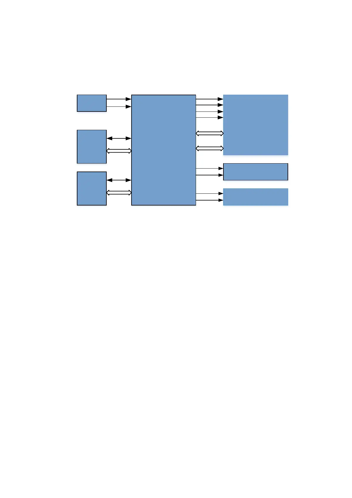
The module is connected with external modules by using BTW, as shown in the following figure.
AC-DC
Module
24V to 12V
Power Conversion
Board
System Mother
Board
Battery
Connecting
Board
Reserved
AC Connecting
Board
Battery
Connecting
Board
24V_ACDC
12V_ACDC
12V_ACDC
24VOUT
J36
J37
BATT1+
BATT2+
Figure 4-14 The connection of 24V to 12V power conversion board and external modules
4.5.4 DC-DC Board
DC-DC module provides public power supply (for example, 12 V, 3.3 V) or specialized power supply
(for example A±5.7 V) to ultrasound service module. It meets the requirements of the voltage and
the current. The service module is able to fulfill the switching of the power supply.
4.5.5 PHV Board
PHV is the acronym of Programmable Height Voltage. The transmission voltage used in the
transmission circuit needs to be adjusted based on varied probes, modes and the depth. Hence, it
requests the program control for the transmission voltage.
PHV module on DC-DC board refers to PHV board.
Absolute value of output voltage is 1.5±5%V~80±5%V; 100 V.
4.5.6 Time Sequence of Power-On
The time sequence of main unit's power-on:
1. Connects AC power supply to main unit.AC-DC outputs the standby power supply 5VSTB by
default to supply the power to EC on PC board. The in-place AC indicator on the control panel
remains on.
2. The user presses the power-on button on the control panel. It triggers PWRBTN_N to supply
EC.
3. EC interacts with PC module according to ATX time sequence. After the standby status of PC
module rises higher, EC notifies AC-DC module of enabling 12_ACDC of non-standby power
supply and outputs to DC-DC module to complete the transfer. Transfers varied power supply,
including PC12 V. After PC12V stays stable, EC module notifies of enabling PC module. Then,
 Loading...


