Product Principle 4-1
4 Product Principle
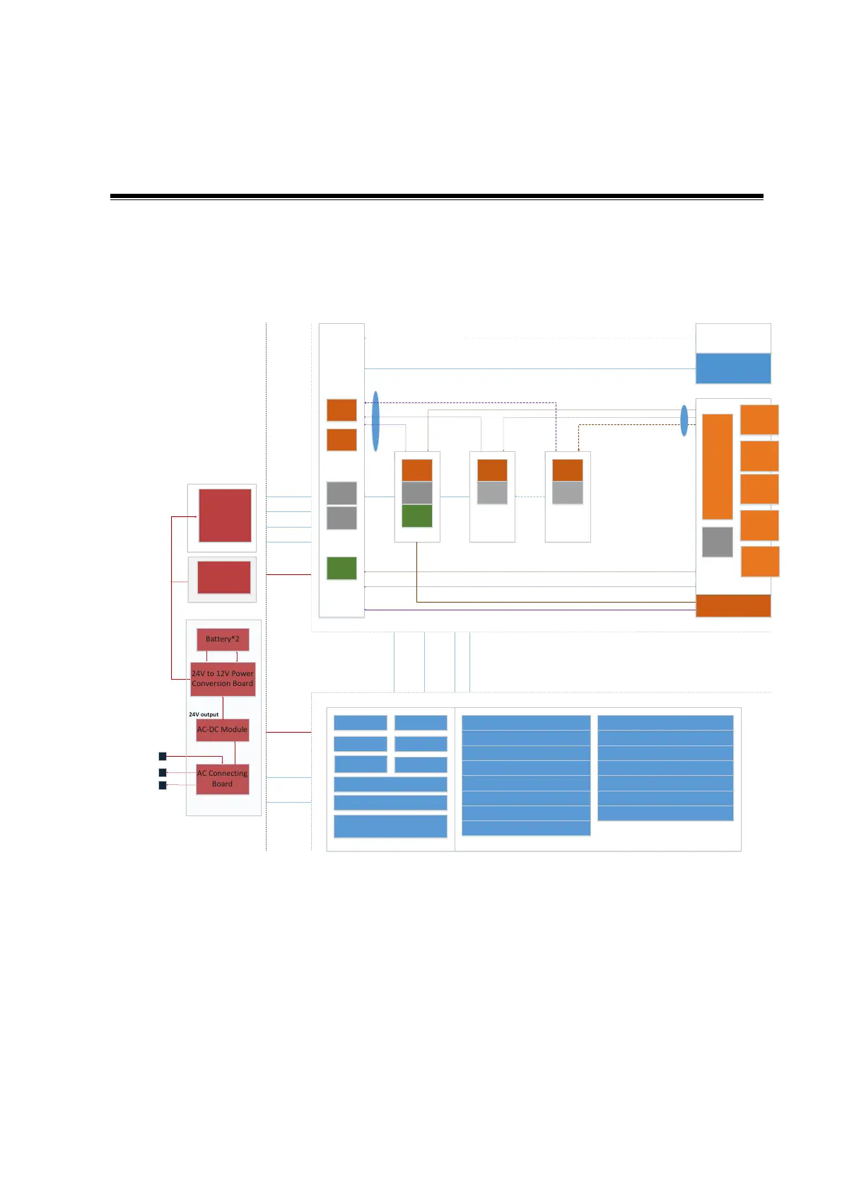
4.1 Hardware System Diagram
PHV Board
TR
FPGA
CW
Board
DSP
FPGA
4D&TEE
Board
Pen Probe Conn
Engine Brd
TR_A Board
Clock
TR
FPGA
TR_B Board
TR
FPGA
TR_C Board
DataDataData
DDR
ATGC
Probe Various Signals
CPLD
Probe
Signal
Switch
Prb Con A
POUT(64)
Present/ID
Probe Board
Power
POUT(64) POUT(64)
Probe Management
PHV Control
Battery*2
24V to 12V Power
Conversion Board
AC-DC Module
AC Connecting
Board
AC Input
TX/RX
TX/RX
TX
RX
TX
RX
TX
RX
Front End
Back End
Power
PHV
Sampling
Scan Status
PHV
Sync
AC output
Control
PHV Control
Monitoring
PCI-E Bus
Reset
Config. Status
JTAG
Touch Screen Device
Hard Disk/DVD-RW
Speaker
Control Panel
Primary Display Device
Secondary Display Device Wireless Network
Digital Video Output
Audio Output
Printer
Analog Video Output
USB Ports
Wired Network
Fans
PC Module
GPU Module
MF FPGA
Back End Monitoring
IO Expansion
DVR Module
PC Unit
PC Manager
Microphone
Medical Positioning
Module
Communication
Physiological Signal
Module
IO Interfaces and Devices
Communication
Reset/Control/Clocks
Auxiliary
Output
for Printer
and User
Prb Con B
Prb Con C
Prb Con D
Prb Con E
24V output
12V output
128G mSATA
SSD
1T
SATA HDD
Bottom Power Box
DC-DC Board
DC-DC
Power
Figure 4-1 of Hardware system diagram
Note: The TR C and TR B boards are reserved, and not configured. The dotted lines are signal
cables connecting to TR C and TR B boards, which are also not configured.
The ultrasound device can be divided into three units according to its functions:
Front-end unit: is in charge of the scan function of the ultrasound imaging system, and sends
the pre-processed imaging data to the back-end unit for post-process. The engine board takes
charge of front-end unit. The elements are shown above:
The uploaded data on TR64 board are wired in daisy chain and sent to the engine board.
 Loading...


