Product Principle 4-3
Figure 4-2 Schematic diagram of ultrasound system front-end
Front-end unit mainly consists of:
Engine board
TR board
Probe board
CW mini board
4D board
The engine board takes charge of the front-end unit and controls each module of the front-end
control.
4.2.1 Probe Board
A-D
Probe
Connector
A-D
Transmit & Receive POUT
128ch x4 (A-D)
probe analog signals
x4 (A-D)
general control
x4 (A-D)
probe digital signals
x4 (A-D)
POUT switch
Analog signal
switch
Manager
Probe
Management
ctrl
ctrl
probe analog signals
e.g. 4D motor/TEE temperature & angle
POUT 128ch or 64ch
JTAG PrbManager_JTAG
probe digital signals
interrupts
Probe Manager Communication
4D&TEE
Board
TR Board
xN
Engine Brd
DSP
FPGA
DC-DC
Board
Probe Board
Mother
Board
HV switch control
Power
±PHV,±HV, 12V, 5V, 3.3V
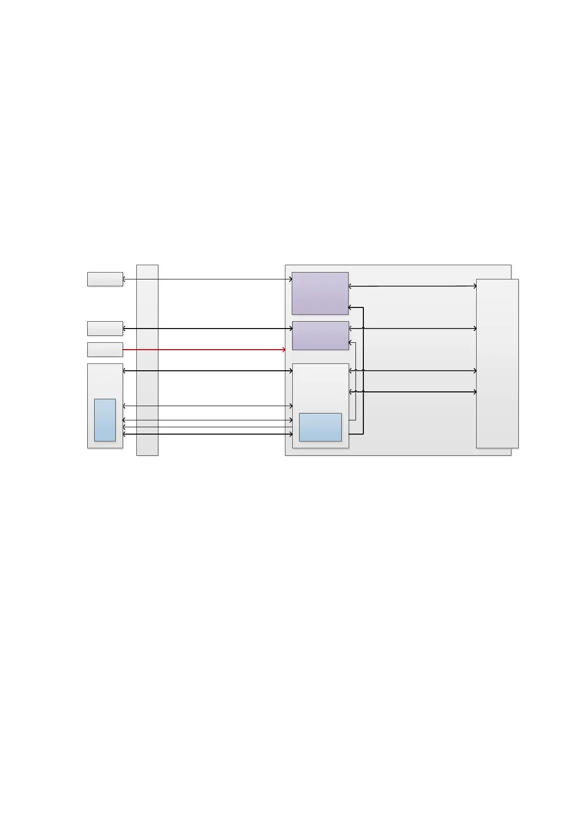
Fig 4-3 Schematic diagram of the probe board
The probe board offers the connection to the probe, and connects the channel of probe's port to the
channel of receiving/transmitting module in main unit. The probe board is subordinate to the engine
board, and manages the probe with the engine board. The functions of probe management:
The notice for probe’s change when it is in the place.
Each in-place signal of the probe is connected to CPLD. CPLD informs DSP_FPGA via an
interruption as each time the change occurs.
General control of the probe - power supply management
CPLD manages the power-up and power-down of each probe’s socket.
Supply the power to flash when accessing to ID as the probe is connected. Enable the probe in
which the channel needs to be switched. The switch circuit inside the probe also needs the
power supply.
After the probe is unplugged, shut down the power supply to the probe and notify the engine
board of stopping transmitting.
General control of the probe -probe recognition
CPLD obtains ID code as SPI accesses to each Flash inside the probe and informs
DSP_FPGA via SPI.
The interconnection to socket's signal
The receiving and transmitting POUT signal of regular probe can be switched among many
probes on the realization of CPLD controlling the relay.
 Loading...


