-
204
-
'15 • HM-T-246
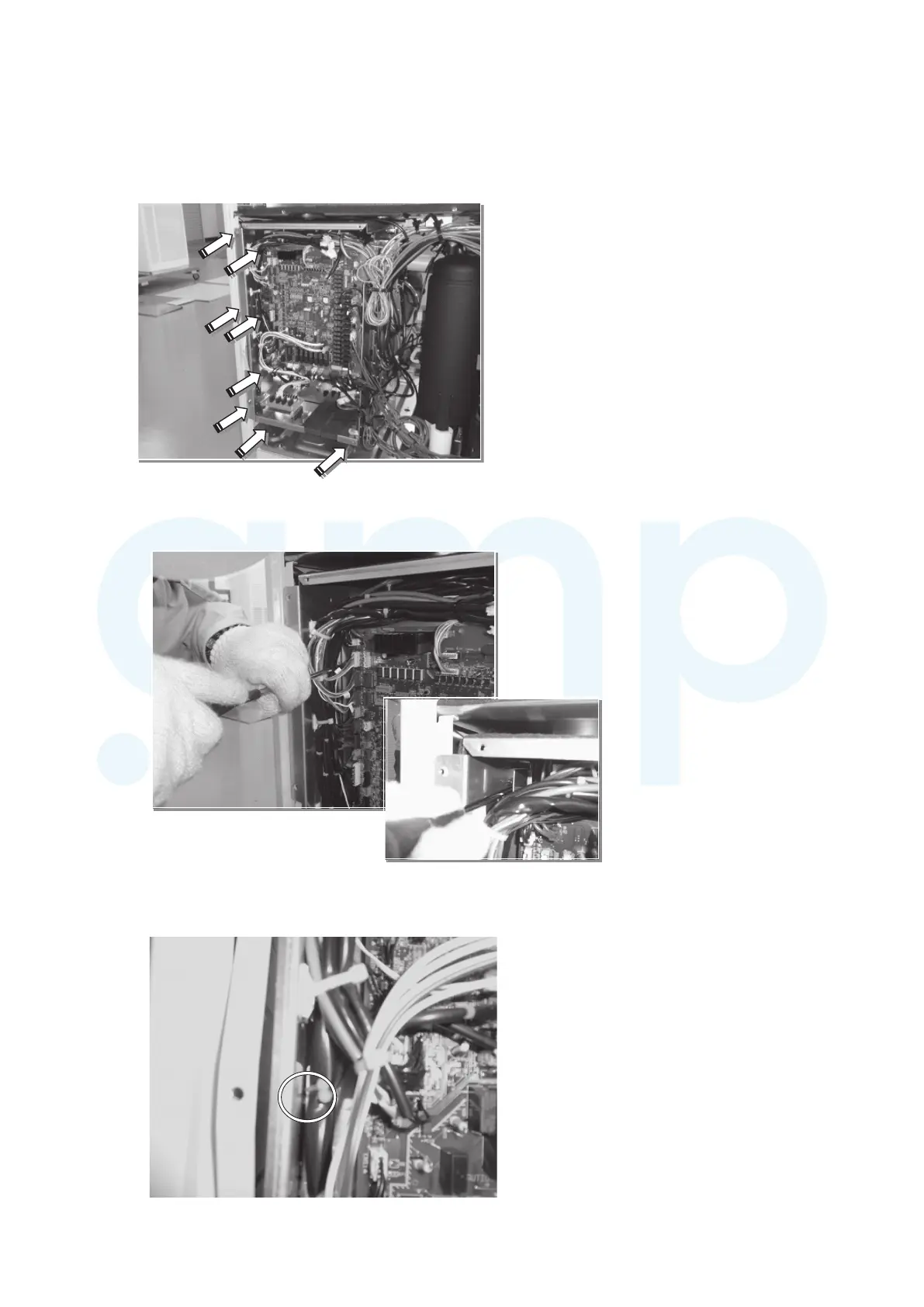
(2) Inverter PCB replacement procedure
(a) Replacement work of inverter PCB (on the third layer)
1) Loosen screws
①
Inside of control box
Be careful not to forget to loosen a center screw
which is hidden by wiring.
The mounting board of the first layer (on the front) the
second layer (on the back) can be removed like as opening
door.
Loosen 8 screws (shown with white arrow)
www.ampair.co.uk | sales@ampair.co.uk
 Loading...