'15 • HM-T-246
-
72
-
(1) Before installation
(Check the model, electrical specifications, piping, necessary option parts and
etc, and install properly.)
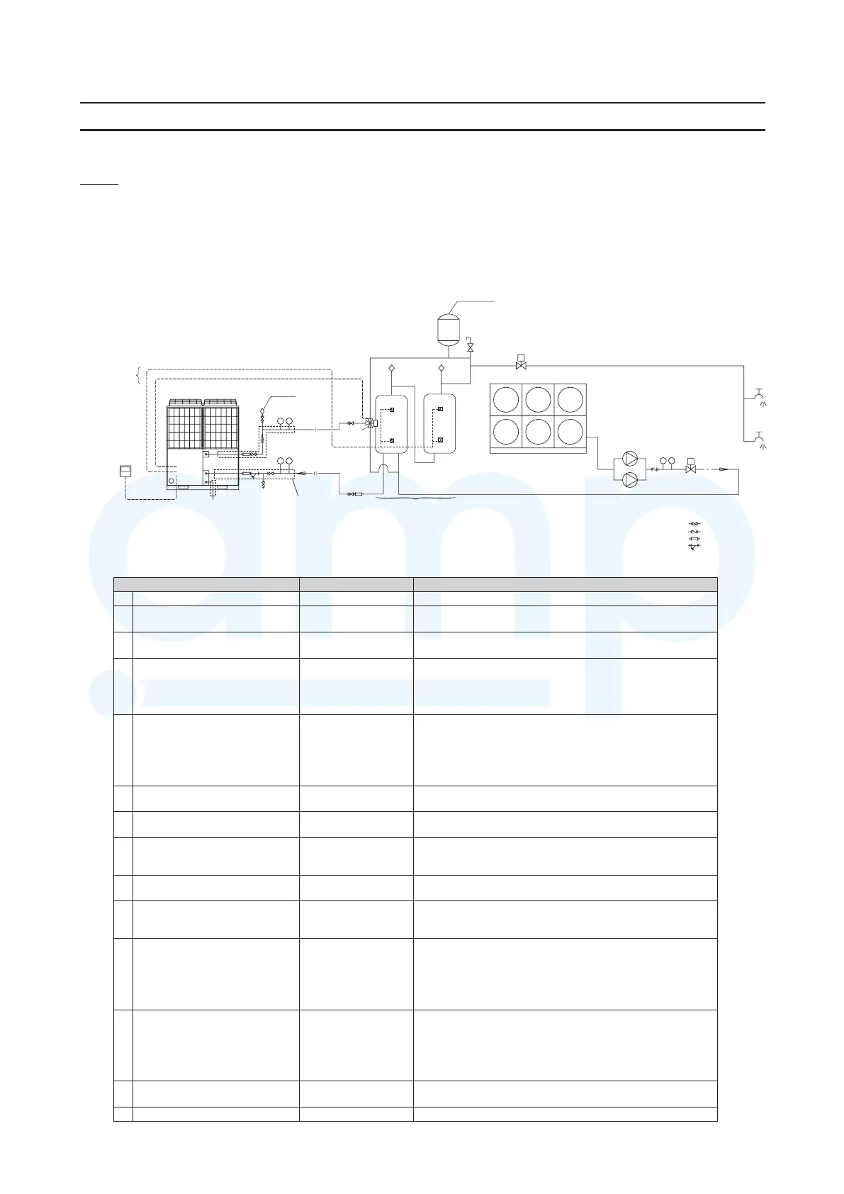
1-1 One way hot water supply system diagram and component list
1-1-1 System diagram
1-1-2 Component list
Wirings for sensors for
unvented cylinder
②Remote
control
④
Wirings for CWFV3
Air purge valve
3-way value,
CWFV3
Hot water temp.
Feed water temp.
GV
GV
GV
FJ
GV
T
P
FJGV
FJYS
Drain
Drain
Clean water cylinder
①ESA30
③Unvented cylinders
T
P
CV
GV:Gate Valve
CV:Check valve
FJ:Flexible joint
YS:Strainer (Y-type)
R
T
P
⑥
Clean water supply
Pressure pump
⑩
Air purge valve
Vessel
⑪
Relief valve
⑧Stop valve. CWFV5
⑥Hot Waler
temp.
⑨Anli-treezing healer
⑫Insulation
⑨
⑨
for unvented cylinder
for water pipings
⑤Pressure
reducing valve
Part name Model General description
①
②
③
(
—
④
•
•
⑤
—
≧
⑥
⑦
⑧
⑨
—
⑩
—
⑪
—
⑫
—
≧
•
m
•
•
⑬
—
⑭
— —
www.ampair.co.uk | sales@ampair.co.uk
 Loading...