NISSEI CORPORATION E6581815
F-19
6
6.7 Simple servo lock function settings
6.7.1 Enabling the simple servo lock function
: Always active function selection 2
: Servo lock function
: Position loop gain
[Parameter Settings]
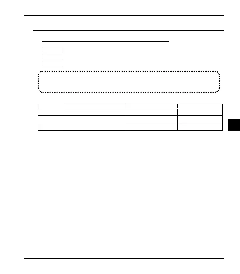
Title Function Adjustment range Default setting
Always active function selection 2 0-153 70 (SVLOCK)
Servo lock function
0: Prohibited
1: Permitted
0
Position loop gain 1-250 100
☆To operate the simple servo lock function, set servo lock function to (Permitted).
☆You can use to adjust the response to load fluctuation during servo lock. Refer to page 6.16 for details.
Note 1: Parameter can be switched during operation. When switching, take care concerning IPM gear motor
operation.
☆With the default setting, function number 70 (servo lock) is assigned to f108 (Always active function selection 2),
setting f257=1 causes the servo lock function always to operate whenever operation is stopped. If you want to
turn the servo lock function on or off using an input terminal, assign function number 70 or 71 (reverse signal of 70) to
an open input terminal, and assign 0 (No function) or some other function to f108.
☆Approximately 150 ms of initial position estimation time (phase detection time) is required until the servo lock input
signal turns ON and operation starts. After that servo lock operation is implemented.
☆The servo lock function is canceled by operation signal ON input. An operation command takes priority.
☆"Sr vo" is displayed during servo lock operation.
☆Assigning "Servo lock braking signal 176, 177 (reverse signal of 176)" or "servo lock signal 178, 179 (reverse signal of
178)" for output terminal selection can be used to check servo lock operation, etc.
Note 2: The motor does not run during servo lock operation, but the inverter operates to stop the IPM gear motor, so
care should be taken to avoid touching the main circuit terminal strip and other parts that can cause electric
shock.
Note 3: The simple servo lock function does not operate when braking mode selection is set to (Enabled).
Braking mode selection takes priority. Keep this in mind when performing operations.
Note 4: When using the simple servo lock function with an IPM gear motor with brake, use " Servo lock braking signal
176 and 177 (reverse signal of 176)" for the brake on/off timing signals.
Note 5: When using an IPM gear motor with brake, do not leave the servo lock engaged for a long period when the
brake circuit is open (brake closed). This can cause motor current to increase and tripping of overload.
Function
・While operation is in standby (operation stopped), performs control that maintains the position in order to
stop the IPM gear motor.
 Loading...