NISSEI CORPORATION E6581815
G-11
7
7.3 Speed instruction (analog signal) settings from
external devices
You can select from voltage input (0 to 10V, 0 to 5V), and current input (4 to 20mA) for an analog input terminal
(VI). The maximum resolution is 1/1000.
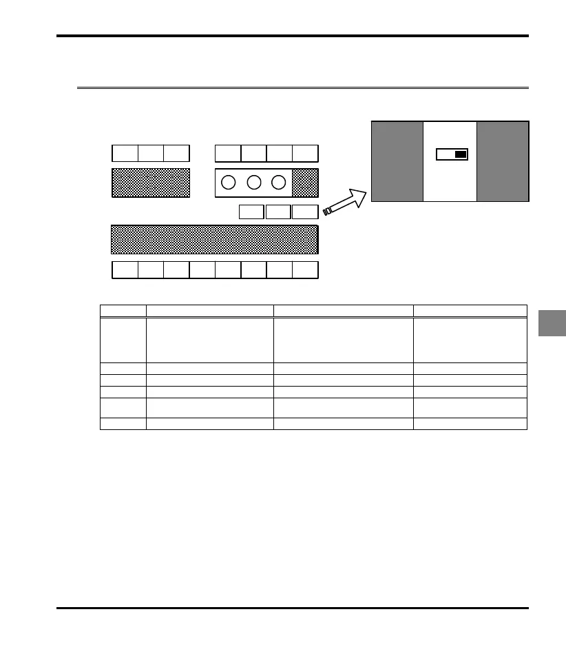
[Control terminal block]
Analog input terminal (VI) function settings
Title Function Adjustment range Default setting
Analog/logic input selection
(VI terminal)
0: Voltage signal input (0 - 10V)
1: Current signal input (4 - 20mA)
2: Logic input
3: Voltage signal input (0 - 5V)
0
Setting of VI input point 1 0 - 100% 0
Frequency of VI input point 1 0.0 - 400.0Hz Note3) 0.0
Setting of VI input point 2 0 - 100% 100
Frequency of VI input point 2
0.0 - 400.0Hz Note3)
0.1k to 0.4kW model : 60.0
0.75k to 2.2kW model : 90.0
Analog input filter 4 - 1000 ms Note1) 64
Note1) When stable operation cannot be attained because of frequency setting circuit noise, increase .
Note2) Semiconductor switch is used to switch between current input and voltage input.
When power supply is off, it is high impedance between VI-CC terminals in spite of current input selecting.
The break detection might operate when current generator (4-20mA) with the break detection function is used.
Please correspond as following to prevent this problem.
1) Solution by sequence
Power supply is switched off inverter and current generator (PLC etc...) at same time with interlock
sequence not to operate break detection function.
2) Solution by external resistor connection
Connect resistor 1/2W-500Ω or 470Ω between VI-CC terminals, and set the following parameter (voltage
input setting). f109=0 (Voltage input : Default setting)
Note3) The permission maximum rotary speed of our IPM gear motor is to 2500 rpm.
Set the frequency 2500 rpm or less.
(Inverter maximum frequency: 0.1k to 0.4kW model: 83.4Hz or less, 0.75k to 2.2kW model: 125Hz or less)
OUT
F
S1
CC
RNO
S2
P24
FLA
FLC
FLB
CC
FM
P5
VI
SW3SW2SW1
SW1
SW2
SW3
LOGIC
RESIST
FM
SOURCE
SINK
OFF
ON
OUT2
FM
 Loading...