NISSEI CORPORATION E6581815
B-4
2
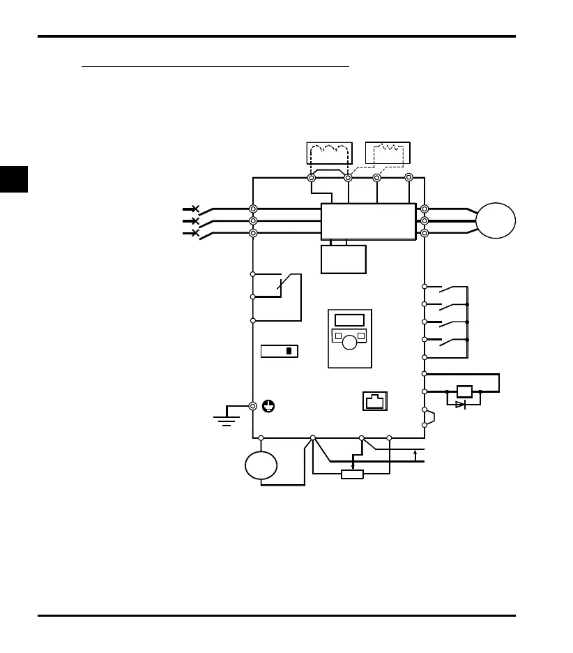
2.2.1 Standard connection diagram 1
This diagram shows a standard wiring of the main circuit.
MCCB
R/L1
S/L2
T/L3
U/T1
V/T2
W/T3
Motor
F
R
S1
S2
CC
P24
OUT
NO
CC
FM
CC VI
P5
++
-
-
P0
PA/+ PC/-
Meter
Voltage signal: 0-5V/0-10V
(Current signal: 4-20mA)
External potentiometer (1k-10k)
Protective function
activation output
Ry
VF-nC3M
Power
circuit
DC reactor (DCL)
*2 (option)
Forward signal
Reverse signal
Preset-speed 1
Preset-speed 2
Common
Standard connection diagram - SINK (Negative) (common:CC)
7.5V-1mA
(or 0-10V/4-20mA)
Brake release
signal output
*3
*2: The inverter is supplied with the PO
and the PA/+ terminals shorted by
means of a shorting bar.
Before installing the DC reactor (DCL),
remove the bar.
*3: When using the OUT output terminal in
sink logic mode, short the NO and CC
terminals.
Control
circuit
IPM
Frequency
me t e r
(ammeter)
Operation panel
FLC
FLB
FLA
*5: When external potentiometer is connected
by using P5 terminal, set the parameter
f109=3.
RS485
communication
connector
*6
*6: When VI terminal is used as a logic
input terminal, refer to page B-7,11.
*5
Main circuit power supply
3ph-240V class: three-phase 200-240V
-50/60Hz
*4
PB
Braking resister(Option)
*1
SINK
SOURCE
SW1
LOGIC
*1: Set the slide switch SW1(LOGIC) to
SINK side.
Refer to page B-9, 10 for details.
Default setting is SINK side.
*4: When using FM terminal as a logic
output terminal, set the slide switch
SW3(FM) to OUT2 side.
 Loading...