NISSEI CORPORATION E6581815
J-3
10
When using the inverter with no magnetic contactor (MC) on the primary side, install a non-fuse circuit
breaker with a voltage tripping coil instead of an MC and adjust the circuit breaker so that it will be tripped if
the protective relay referred to above is activated. To detect a power failure, use an undervoltage relay or
the like.
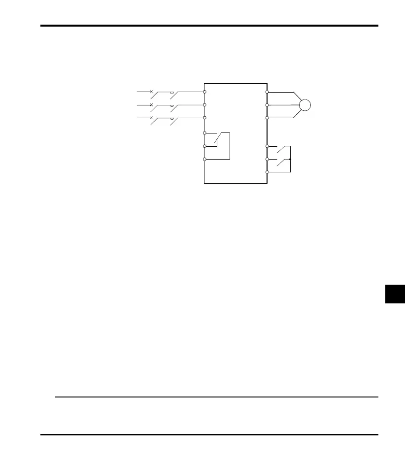
Example of connection of a magnetic contactor in the primary circuit
Notes on wiring
When frequently switching between start and stop, do not use the magnetic contactor on the primary side as
an on-off switch for the inverter.
Instead, stop and start the inverter by using terminals F and CC (forward run) or R and CC (reverse run).
Be sure to attach a surge killer to the exciting coil of the magnetic contactor (MC).
Magnetic contactor in the secondary circuit
If the motor is turned by 3000rpm (motor axis conversion) or more from the load side, the inverter may
result in malfunction depending on the inductive voltage generated by the motor even if the inverter is
stopped state. Please adopt the circuit which put a switch in the output side of the inverter by all means,
when a motor may be turned by load.
Notes on wiring
Be sure to interlock to prevent the switch operates during driving the inverter.
When installing a magnetic contactor (MC) between the inverter and the motor, avoid turning the magnetic
contactor on or off during operation. Turning the magnetic contactor on or off during operation causes a current
to rush into the inverter which could lead to malfunction.
10.3 Installation of an overload relay
1) This inverter has an electronic-thermal overload protective function.
When shipped from our company, the motor electronic-thermal protection level is set to default setting for
each IPM Gear Motor.
MC
VF-nC3M
R/L1 U/T1
W/T2
W/T3
F
R
CC
S/L2
T/L3
FLC
Forward run
Reverse run
Motor
FLB
FLA
MCCB
Power supply
 Loading...