4-70
4-2 Function Mode
4
Functions
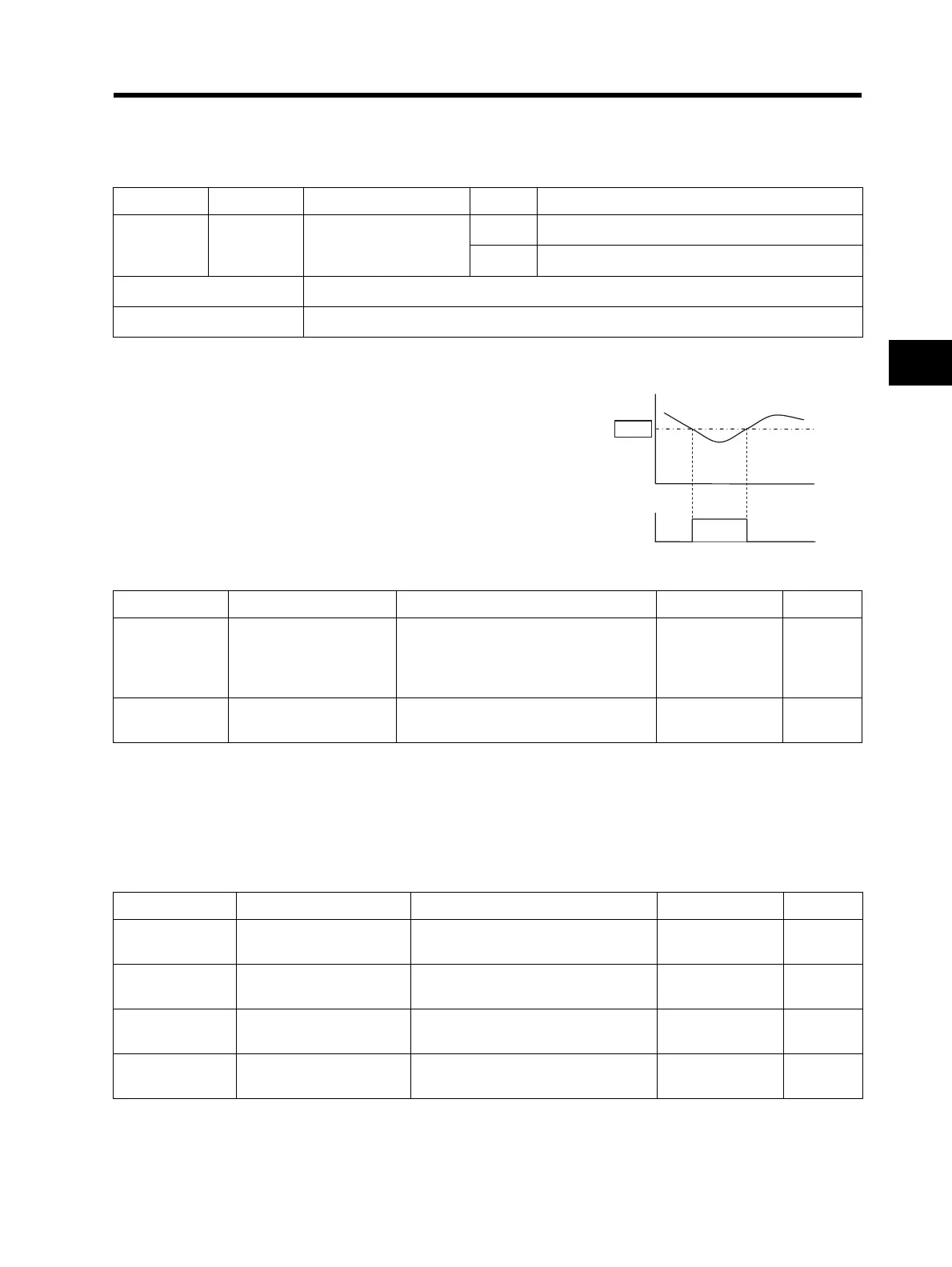
Light Load Detection Signal
This function outputs a signal when the Inverter output current has fallen below the C039 set value.
Multi-function Output Terminal ON Delay/OFF Delay
This function allows you to set ON/OFF delay times respectively from 0.1 to 100 seconds at the
signal output of the multi-function output terminals (P1 and relay). The following figure shows the
output status.
Data Symbol Function name Status Description
43 LOC
Light load detection
signal
ON Output current is lower than the C039 set value.
OFF Output current is higher than the C039 set value.
Available input terminals P1-PC, MA-MC (or MB-MC)
Required settings C021, C026, C038, C039
The signal is output if the load current has fallen below
the C039 set value with the light load signal output
mode set to 00 or 01 in C038, and LOC (43) allocated
to the multi-function output terminal.
This function helps avoid a trip resulting from a falling
motor current.
Output
current
C039
0
[LOC]
output
1
0
t
t
Parameter No. Function name Data Default setting Unit
C038
Light load signal output
mode
00: Enabled during acceleration,
constant speed, and deceleration
01: Enabled only during constant
speed
01 ⎯
C039
Light load detection
level
0.0 to 2.0 × Rated current
0.0: Does not operate
Rated current A
Parameter No. Function name Data Default setting Unit
C144
Output terminal P1
ON delay
0.0 to 100.0 0.0 s
C145
Output terminal P1
OFF delay
0.0 to 100.0 0.0 s
C148
Relay output
ON delay
0.0 to 100.0 0.0 s
C149
Relay output
OFF delay
0.0 to 100.0 0.0 s
 Loading...


