4-12
4-2 Function Mode
4
Functions
Jogging Operation Function
The motor rotates while the input is turned ON.
For details on the operation and settings, refer to "Jogging Operation" (page 4-48).
•The Inverter runs at the speed set in A038 while the JG terminal allocated to one of the multi-
function input terminals is turned on. Stop selection is also available in A039.
Relation Between Torque Boost and V/f Characteristics
Determine the relation of output voltage against output frequency.
* To switch to the 2nd control, allocate 08 (SET) to the multi-function input terminal and then turn it on.
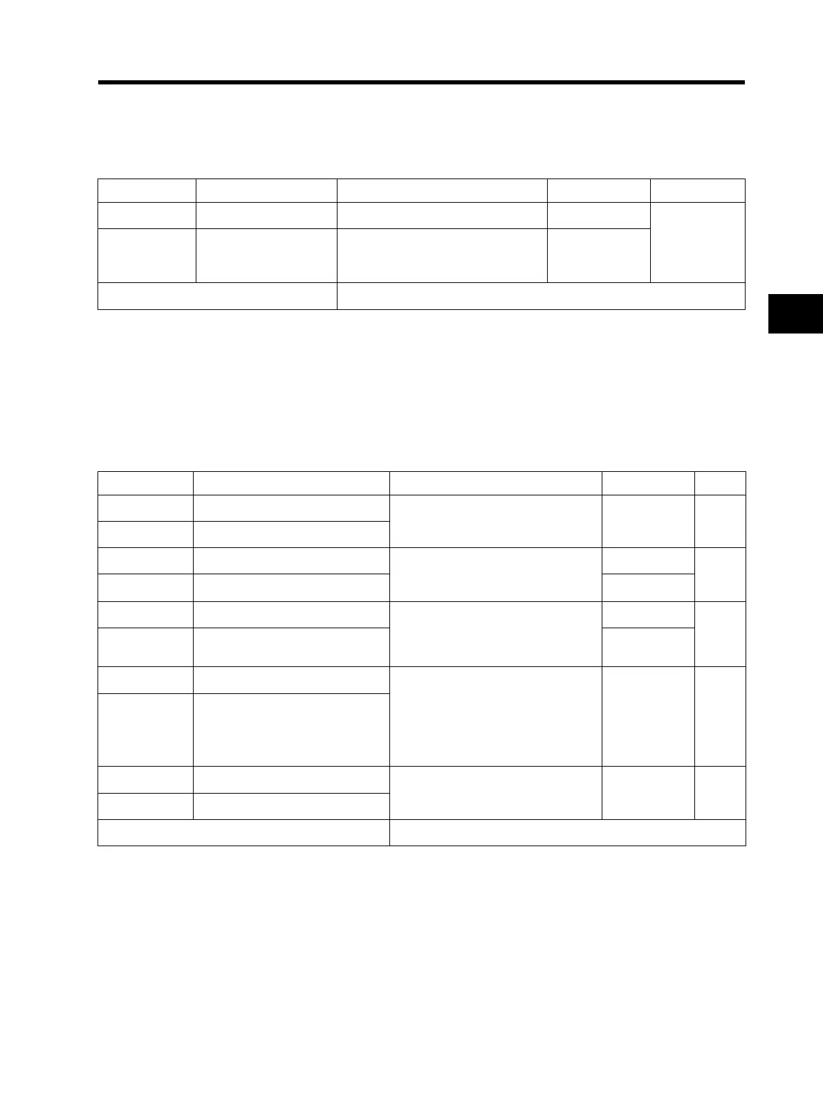
Parameter No. Function name Data Default setting Unit
A038 Jogging frequency 0.00/Starting frequency to 9.99 6.00
Hz
A039 Jogging stop selection
00: Free-run stop
01: Deceleration stop
02: DC injection braking stop
00
Related functions C001 to C005, JG input
Parameter No. Function name Data Default setting Unit
A041 Torque boost selection
00: Manual torque boost
01: Automatic (simple) torque boost
00 ⎯
*
A241 2nd torque boost selection
A042 Manual torque boost voltage
0.0 to 20.0
(Ratio to the value of AVR voltage
selection A082)
5.0
%
*
A242 2nd manual torque boost voltage 0.0
A043 Manual torque boost frequency
0.0 to 50.0
(Ratio to base frequency)
2.5
%
*
A243
2nd manual torque boost
frequency
0.0
A044 V/f characteristics selection
00: Constant torque characteristics
(VC)
01: Reduced torque characteristics
(VP 1.7th power)
06: Special reduced torque
characteristics (Special VP)
00 ⎯
*
A244 2nd V/f characteristics selection
A045 Output voltage gain
20. to 100. 100. %
A245 2nd output voltage gain
Related functions A082, H003/H203, H004/H204
 Loading...


