4-80
4-2 Function Mode
4
Functions
ModBus Communication Protocol
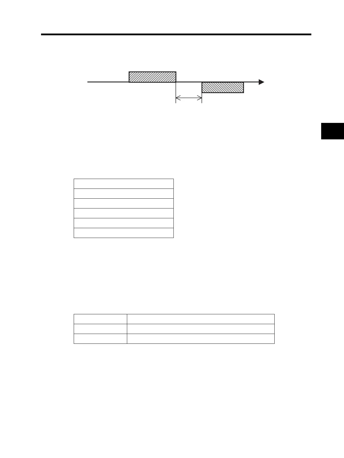
Follow the procedures below in regard to communication between the external controller and the
Inverter.
(1): Frame to be sent from the external controller to the Inverter (Query)
(2): Frame to be returned from the Inverter to the external controller (Response)
The Inverter returns a response (Frame (2)) only after receiving a query (Frame (1)) and does not
output a response positively.
Each frame format (command) is shown below.
Message configuration: Query
<Slave Address>
•Pre-set numbers ranging from 1 to 32 in each Inverter (slave). (Only the Inverter having the same
slave address as the query takes in the query.)
•Broadcasting can be performed by setting the slave address to "0".
•Data call or loopback cannot be performed while broadcasting.
<Data>
•Sends the function command.
•The 3G3JX corresponds with the following data formats used in the ModBus.
<Function Code>
•Specifies a function for the Inverter to perform.
•The function codes available to the 3G3JX are shown on the next page.
Header (Silent interval)
Slave address
Function code
Data
Error check
Trailer (Silent interval)
Data name Description
Coil Binary data (1-bit long) that can be referred to or changed
Holding register 16-bit long data that can be referred to or changed
External controller
Inverter
(1)
(2)
Time
Wait time (silent interval +C078)

 Loading...


