2-2
2-1 Installation
2
Design
Transporting, Installation, and Wiring
•Do not drop or apply strong impact on the product. Doing so may result in damaged parts or malfunction.
•Do not hold by the front cover, but hold by the fins during transportation.
•Do not connect an AC power supply voltage to the control input/output terminals. Doing so may result in
damage to the product.
•Be sure to tighten the screws on the terminal block securely.
Wiring work must be done after installing the unit body.
•Do not connect any load other than a three-phase inductive motor to the U, V, and W output terminals.
•Take sufficient shielding measures when using the product in the following locations. Not doing so may
result in damage to the product.
Locations subject to static electricity or other forms of noise.
Locations subject to strong magnetic fields.
Locations close to power lines.
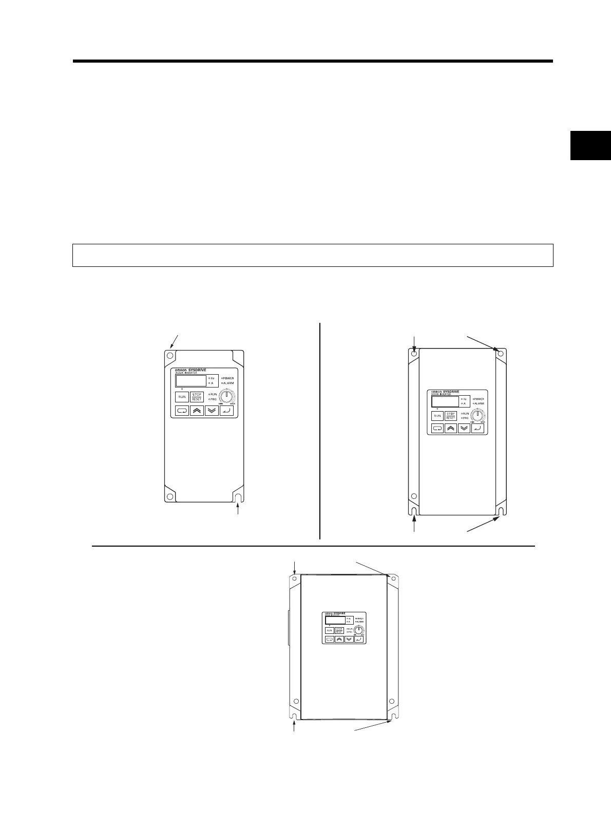
Installation
•Install the Inverter vertically on the wall or DIN tracks (optional).
Install the Inverter on a nonflammable wall surface material, like metal.
Precautions for Use
Position for installing a screw
Model
3G3JX-A2002
A2004
A2007
AE002
AE004
Screw size for
installation: M5
Position for installing a scre
Positions for installing screws
Positions for installing screws
Model
3G3JX-A2015
A2022
A2037
A4004
A4007
A4015
A4022
A4037
AE007
AE015
AE022
Screw size for
installation: M5
Position for installing a scre
Model
3G3JX-A2055
-A2075
-A4055
-A4075
Screw size for
installation: M6
Position for installing a screw

 Loading...


