2-14
2-2 Wiring
2
Design
Choose the sensitivity current of the earth leakage breaker (ELB), depending on the total distance (L) between
the Inverter and the power supply, and the Inverter and the motor.
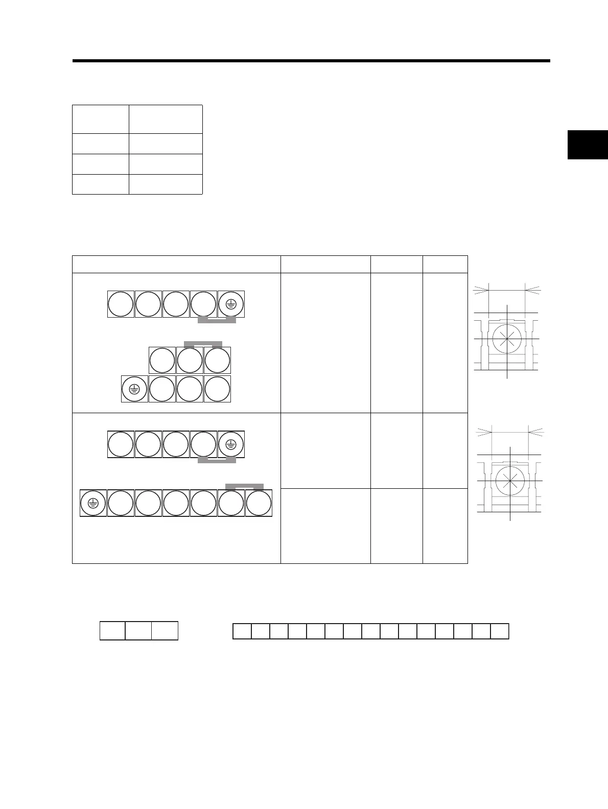
Terminal Arrangement
*1. For 3G3JX-AE, R/L1 corresponds to L1, S/L2 to L2, and T/L3 to N/L3.
Connect a single-phase 200-V AC input to terminals L1 and N/L3.
L
Sensitivity
current (mA)
Guide of leakage current: If a CV wire is used and routed through a metal pipe,
the leakage current is 30 mA/km.
Due to the higher specific inductive capacity of the H-IV wire, the leakage current
increases about eight times. Use a wire with a sensitivity current one-level higher.
The leakage current mentioned here is the effective value of the fundamental
wave, and high-frequency currents are excluded.
100 m max. 30
300 m max. 100
800 m max. 200
Main circuit terminal block Model (3G3JX-) Screw size W (mm)
Upper side of the body
Lower side of the body
A2002 to A2007
AE002 to AE004
(*1)
M3.5 7.1
Upper side of the body
Lower side of the body
A2015 to A2037
A4004 to A4037
AE007 to AE022
(*1)
M4 9.2
A2055 to A2075
A4055 to A4075
M5 13
7.1
Main Circuit
Terminal Bloc
9.2 or 13
Main Circuit
Terminal Block
R/L1 S/L2 T/L3
N/- P/+2 +1
U/T1 V/T2
W/T3
R/L1 S/L2 T/L3
U/T1 V/T2 W/T3 N/- P/+2 +1
Relay Output
Terminal Block
MB MA MC
Control Circuit Terminal Block
AM FS FV FI FC S5
S4 S3 S2 S1 SC PSC P24 PC P1