2-18
2-2 Wiring
2
Design
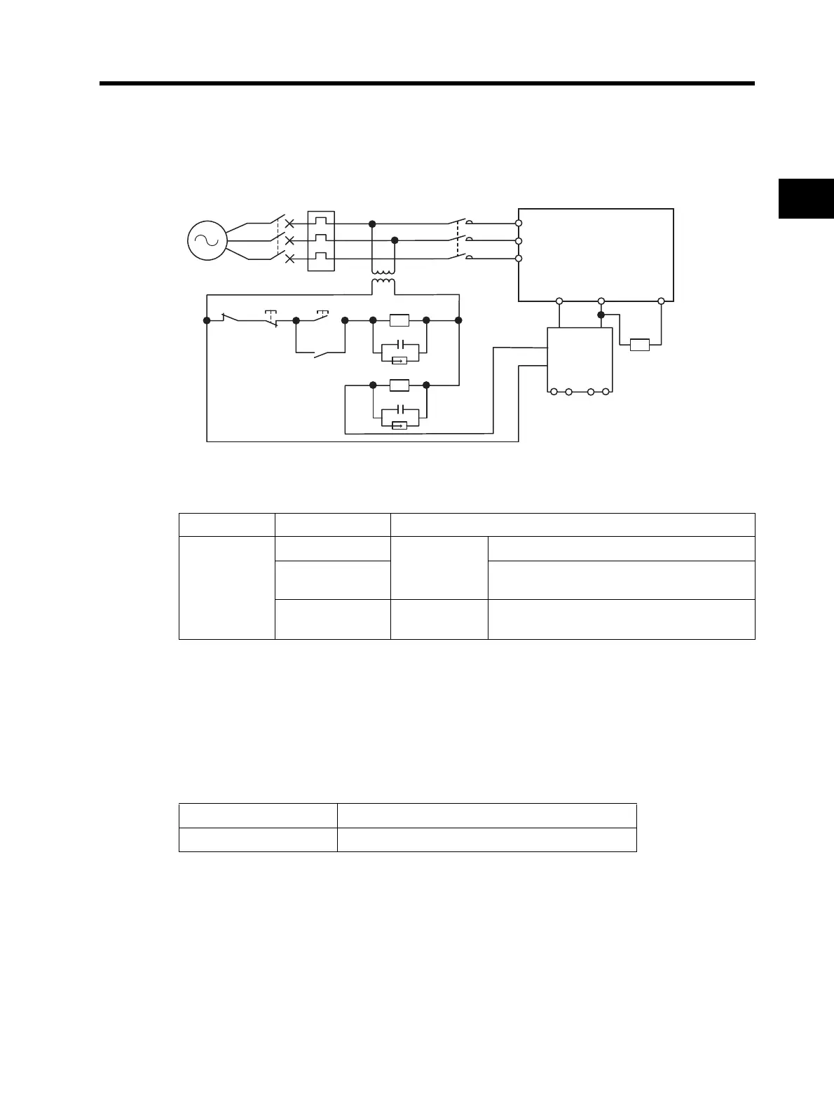
•When using a regenerative braking unit, be sure to include a sequence whereby the power supply
for the Inverter will be turned off in the event of abnormal overheating. Not doing so may result in
fire.
For a regenerative braking unit: Use the error contact output (MA, MB).
* The items in parentheses indicate terminal symbols for 3G3JX-AE.
<Braking Resistors and Braking Resistor Units for the Inverter>
Installing a Noise Filter on the Input Side
•The Inverter's output uses high-speed switching, so noise may be transmitted from the Inverter to
the power line, affecting peripheral devices.
•It is recommended that a noise filter be installed on the input side to minimize noise transmission.
(Installing a noise filter on the input side can also reduce the noise from the power line to the
Inverter.)
<Recommended Input Noise Filters for the Inverter>
Molded-case
circuit breaker
(MCCB)
MC
Power supply
OFF ON
MC
SA
R/L1 (L1) *
S/L2 (L2)
T/L3 (N/L3)
N/- P/+2 +1
DCL
DC reacto
NP
PRB R1R2
MC
XB
SA
MC
AL1
AL2
Regenerative braking unit
Magnetic contactor
(MC)
Inverter
3G3JX
Name Model Specifications
Regenerative
braking unit
3G3AX-RBU21
3/1-phase
200 V
For general use (with built-in resistor)
3G3AX-RBU22
For heavy instantaneous regenerative power
(with built-in resistor)
3G3AX-RBU41
3-phase
400 V
For general use (with built-in resistor)
General EMC-conforming
3G3AX-NFI 3G3AX-EFI
 Loading...


