4-33
4-2 Function Mode
4
Functions
<ASCII (C078 = 00)>
Transfer data using "command 01". To transfer feedback data, set the most significant byte of
frequency data to "1".
(Example) To send 5 Hz:
Transmission data is "set value × 100" and expressed in 6 bytes
"000500"
Set the most significant byte to "1".
"100500"
ASCII conversion
"31 30 30 35 30 30"
Note: With ASCII data, the set value is frequency (Hz).
<ModBus-RTU (C078 = 01)>
Write data in holding register address 0006h. (100% = 10000)
Note: You can read and write data. However, you can read data only when ModBus-RTU is selected for the PID
feedback. Data cannot be read under other settings.
•If "03" (pulse train input) is set for PID feedback A076, the Inverter obtains a percent conversion
result (100% at max. frequency) as a feedback value, relative to the input pulse train frequency
value (Hz).
Feedforward Selection
•Select a terminal used for feedforward signals in PID feedforward selection A079.
•The A079 setting is enabled even if the terminal selected in A079 is duplicated with the terminal
selected for target value or feedback value input.
•If A079 is set to "disabled", feedforward control is disabled.
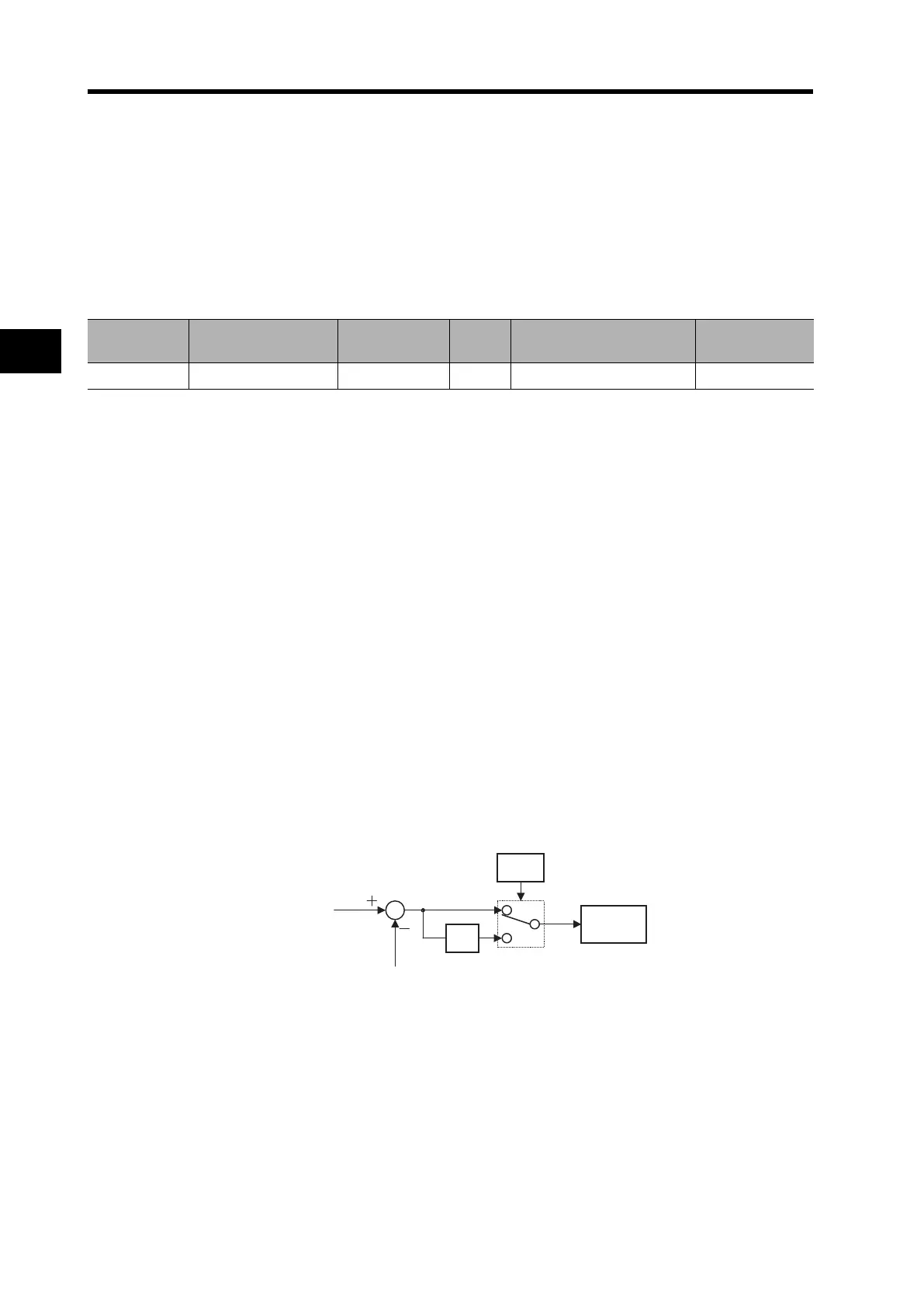
Reverse PID Function
Depending on the sensor characteristics, the polarity of deviation between the target and feedback
values may not match the Inverter's command. In this case, you can invert the deviation polarity by
setting A077 to "01".
(Example) To control a refrigerator compressor:
If the specified temperature range of a temperature sensor is -20C to 100C at 0 to
10 (V), the target value is 0C, and the current temperature is 10C, the Inverter
reduces the frequency under normal PID control since the feedback value is higher
than the target value.
Set A077 to "01" so that the Inverter increases the frequency.
Register No. Function name Function code R/W
Monitor data and setting
parameters
Data resolution
0006h PID feedback R/W 0 to 10000 0.01 [%]
PID target value
PID feedback value
-1
A077
PID operation