E 12.1
50.00Hz
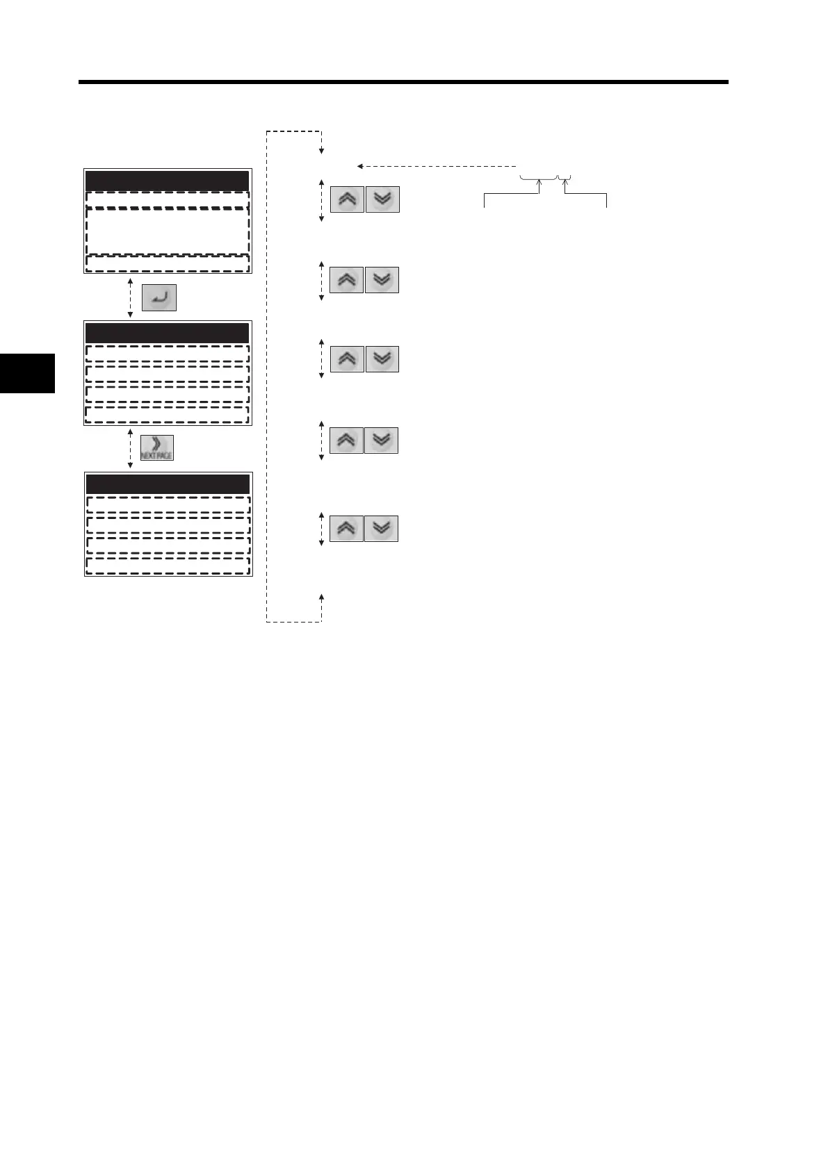
(2) Output frequency (Hz) at the time of tripping
4.00A
(3) Output current (A) at the time of tripping
400.2 Vdc
(4) P-N DC voltage (V) at the time of tripping
15hr
(5) Total RUN time (h) before the trip
8hr
(6) Total power ON time (h) before the trip
(1) Trip factor Explanation of display
E 12.1
Indicates the cause of the trip.
Indicates the Inverter status at the time of tripping.
1
: During stop
0
: During initialization at power-on or with
the reset terminal set to ON.
2
: During deceleration
3
: During constant speed
4
: During acceleration
5
6
: During startup
7
: During DC injection braking
8
: During overload limit
9
: During forcing/servo ON
Note: The trip monitor display shows the Inverter status
at the time of tripping, not the actual motor operation.
(Example)
While PID control is used or the frequency reference
is input using analog signals (voltage/current), the
Inverter may alternate frequently between
acceleration and deceleration because of the signal
fluctuations, even if the motor seems to operate at a
constant speed.
In this case, the onscreen lnverter status at the time
of tripping may differ from the actual operation.
TRIP M1-STOP ALL
ERR1 P2 Ext. Trip
ON time 8hr
DC Voltage 400.2Vdc
RUN time 15hr
TRIP M1-STOP ALL
ERR1 P1 Ext. Trip
Output current 4.00A
111006 11:05 Stop
Output FQ 50.00Hz
TRIP M1-STOP ALL
E12.1
111006 11:05 Stop
Ext. Trip
: The RUN command is turned on at frequency: 0.
 Loading...


