4-146
4-4 Communication Function
4
Functions
Single wire 0.14 to 1.5 mm
2
(If two equal-sized wires are connected to one pole:
0.14 to 0.5 mm
2
)
Stranded wire 0.14 to 1.0 mm
2
(If two equal-sized wires are connected to one pole:
0.14 to 0.2 mm
2
)
Stranded wire with solderless terminal 0.25 to 0.5 mm
2
Wire strip length 5 mm
Tightening torque 0.22 to 0.25 N•m (screw size: M2)
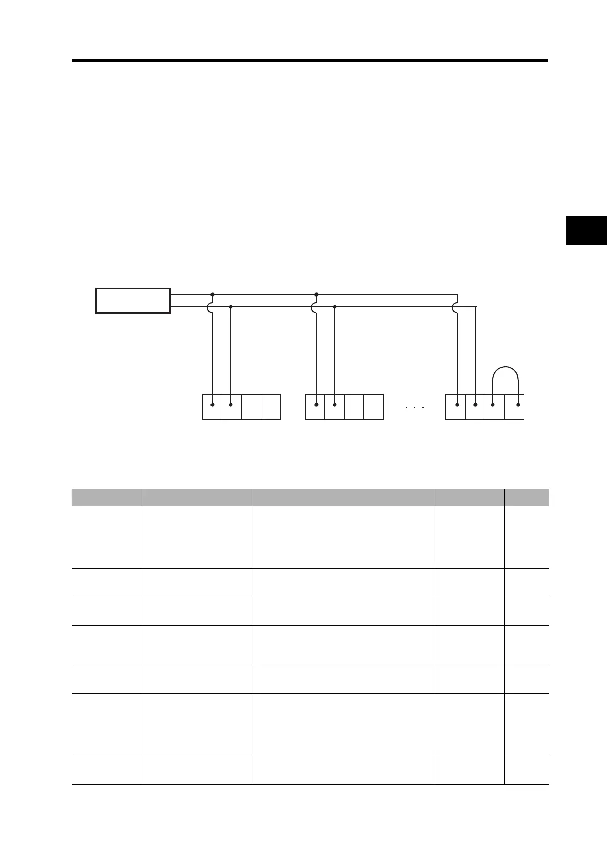
•Connection
Connect the Inverters parallel to each other, as shown below. For the termination Inverter, short-
circuit the RP and SN terminals. (Also, if the RS485 communication function is used with a single
Inverter, the RP and SN terminals must be short-circuited.)
Short-circuiting the RP and SN terminals activates the termination resistor inside the control
terminal block board, suppressing signal reflection.
Setting
RS485 communication requires the following settings.
External controller
SP SNRPSN SP SN
RP
SN SP SNRPSN
Parameter No. Function name Data Default setting Unit
C071
Communication speed
selection
(Baud rate selection)
02: Loop-back test
03: 2400 bps
04: 4800 bps
05: 9600 bps
06: 19200 bps
05
C072
Communication station
No. selection
1 to 247 1
C073
Communication bit
length selection
7: 7-bit
8: 8-bit
8
C074
Communication parity
selection
00: No parity
01: Even
02: Odd
00
C075
Communication stop bit
selection
1: 1-bit
2: 2-bit
1
C076
Communication error
selection
00: Trip
01: Decel-Trip (Trip after deceleration stop)
02: Ignore
03: Free-RUN (Free-run stop)
04: Decel-Stop (Deceleration stop)
02
C077
Communication error
timeout
0.00 to 99.99: Communication
disconnection judgment time
0.00 s
 Loading...


