4-102
4-2 Function Mode
4
Functions
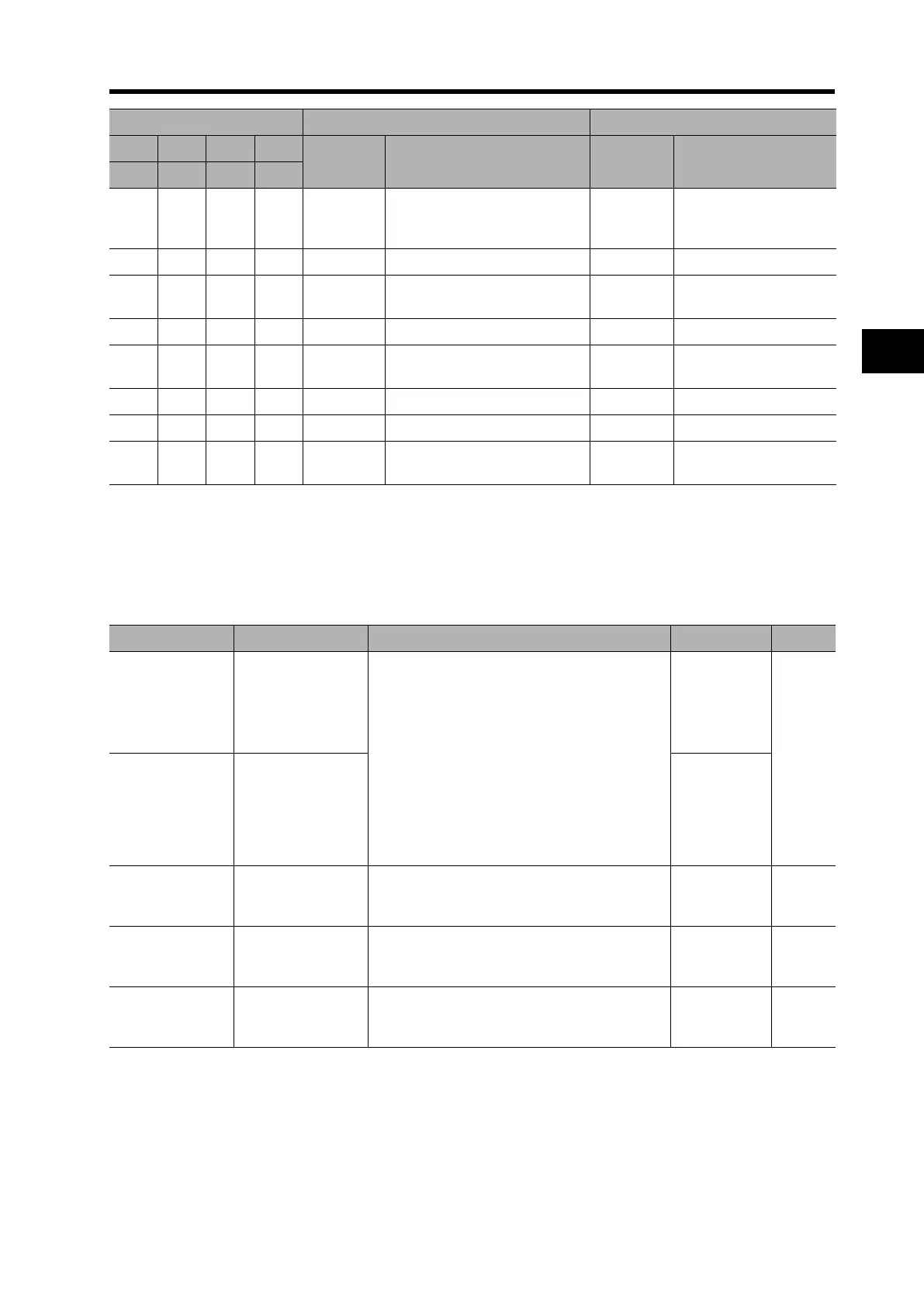
Output Signal Logic Operation
•This function performs output signal logic operations inside the Inverter.
•All output signals are operation targets.
However, the logic operation outputs (LOG1 to LOG6) are not subject to operations.
1000
E08, E11
E23, E25
EEPROM error, CPU error,
GA communication error, Main
circuit error
1001 E10CT error
1010
E12, E13
E35, E36
External trip, USP error,
Thermistor error, Brake error
1 1 0 0 E14 Grounding protection
1101 E20
Abnormal temperature due to
the cooling fin's speed drop
1 1 0 1 E21 Abnormal temperature
1 1 1 0 E24 Input phase loss protection
1111E50 to E79
Network error, Options 1, 2
Errors 0 to 9
Multi-function output terminals With 4-bit code selected With 3-bit code selected
14 13 12 11
Factor code Trip cause Factor code Trip cause
AC3 AC2 AC1 AC0
Parameter No. Function name Data Default setting Unit
C021 to C025
Multi-function
output terminal 11
to 15 selection
33: LOG1
(Logic operation output [C142, C143, C144])
34: LOG2
(Logic operation output 2 [C145, C146, C147])
35: LOG3
(Logic operation output 3 [C148, C149, C150])
36: LOG4
(Logic operation output 4 [C151, C152, C153])
37: LOG5
(Logic operation output 5 [C154, C155, C156])
38: LOG6
(Logic operation output 6 [C157, C158, C159])
C026
Relay output
(AL2, AL1) function
selection
05
C142/C145/C148/
C151/C154/C157
Logic output signal
selection 1
Select 00 to 50 from the multi-function output
data (other than LOG1 to LOG6):
Select operand 1.
00
C143/C146/C149/
C152/C155/C158
Logic output signal
selection 2
Select 00 to 50 from the multi-function output
data (other than LOG1 to LOG6):
Select operand 2.
00
C144/C147/C150/
C153/C156/C159
Logic output signal
operator selection
00: AND
01: OR
02: XOR
00
 Loading...


